Broad band deep ultraviolet/vacuum ultraviolet catadioptric imaging system

a catadioptric optical and deep ultraviolet technology, applied in the field of optical imaging, can solve the problems of difficult color correction in the uv, duv, vuv wavelength range, glass dispersion greatly increases, etc., and achieves the effect of relaxing manufacturing tolerances, increasing spectral bandwidth, and increasing spectral bandwidth

Inactive Publication Date: 2001-11-15
KLA TENCOR TECH CORP
View PDF0 Cites 57 Cited by
  • Summary
  • Abstract
  • Description
  • Claims
  • Application Information

AI Technical Summary

Benefits of technology

0035] Several additional embodiments describe the optical apparatus in the following detailed description. Two basic catadioptric objective design approaches are employed in these embodiments. Both approaches take advantage of multiple internal images for aberration correction and to produce a design with no central obscuration. The first design approach uses a reflective lens mirror element that is folded such that the optical axis is at an angle to the optical axis of the major refractive components. The second design approach uses a reflective lens mirror element that has its optical axis mostly coincident with the optical axis of the major refractive components. Each of these design approaches can correct for at least 1 nm of spectral bandwidth at 193 nm using a single glass material. The design can also correct for 0.5 nm of spectral bandwidth at 157 nm. Addition of a second glass material provides the ability to increase spectral bandwidth. For example, at 193 nm, the spectral bandwidth can be increased to greater than 10 nm using silica and CaF.sub.2 glass.
0036] The second design approach has the optical axis of a Mangin mirror coincident or nearly coincident with the optical axis of the refractive components. This design provides relatively relaxed manufacturing tolerances and increased design flex...

Problems solved by technology

Color correction in the UV, DUV, and VUV wavelength ranges is increasingly difficult.
At shorter wavelengths, the glass dispersion greatly increases and is difficult to correct.
Minimizing the number of glass materials used in a UV, DUV or VUV optical system produces special challenges for correcting color aberrations.
Standard color correction is not possible because no other glass material is available.
Another problem with currently available systems is that such systems provide a relatively short working distance between the optical system and the surface being inspected.
A further problem with currently available systems is that while some relatively high NA systems exist, the central returning rays may be obscured due to apertures and other optical components.
Such a central obscuration blocks low frequency information from the image and is undesirable.
A system having an internal pupil plane is undesirable because it does not readily support aperturing, particularly variations in aperture shapes, and Fou...

Method used


Image

  • Broad band deep ultraviolet/vacuum ultraviolet catadioptric imaging system
  • Broad band deep ultraviolet/vacuum ultraviolet catadioptric imaging system
  • Broad band deep ultraviolet/vacuum ultraviolet catadioptric imaging system

Examples


second embodiment

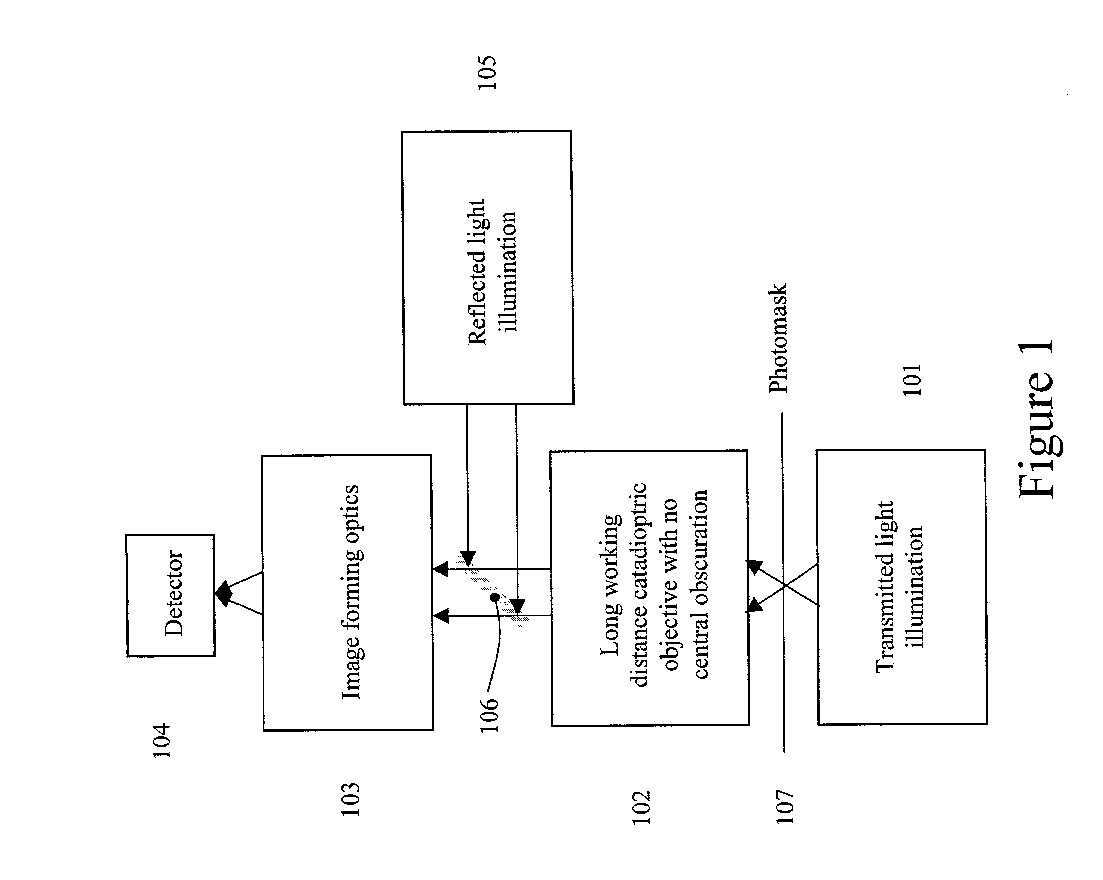
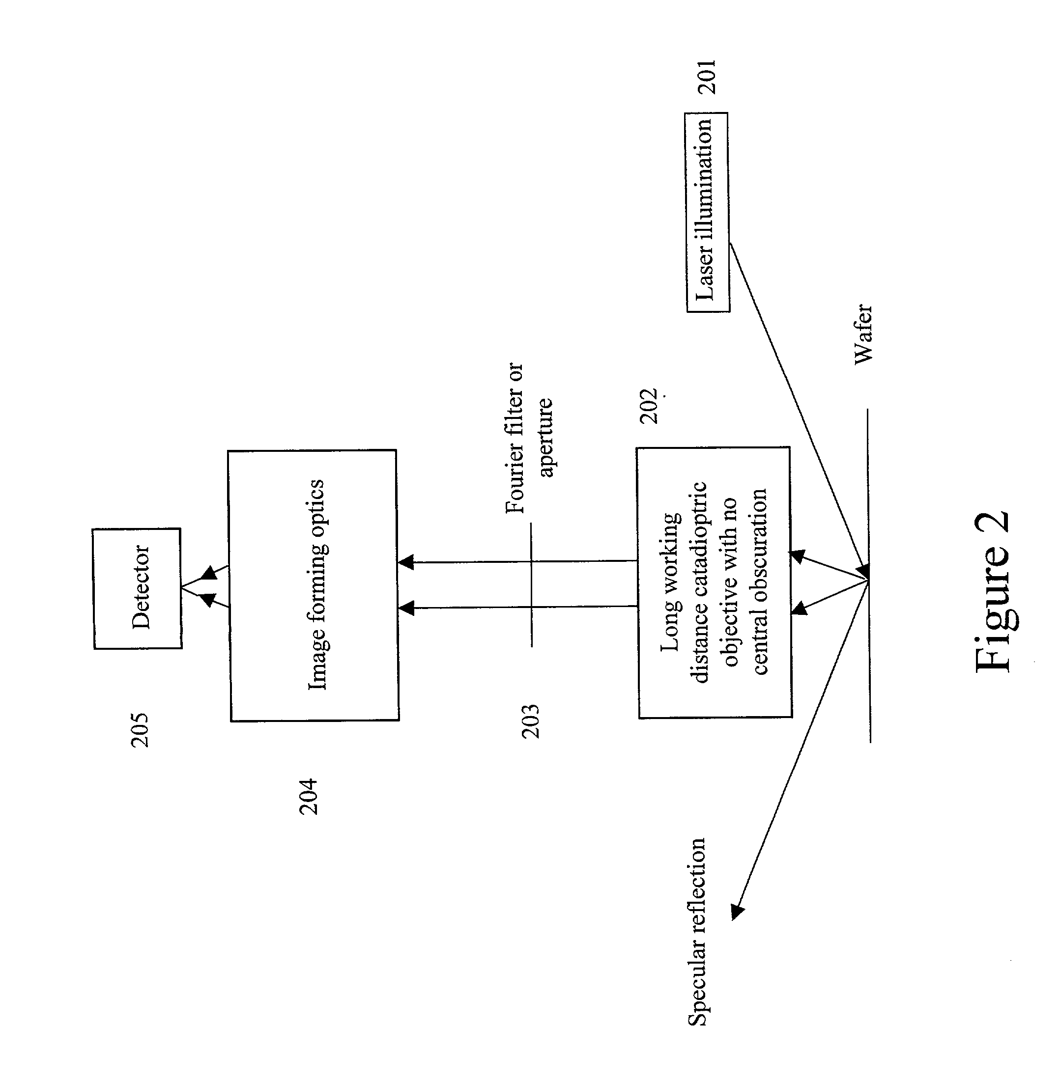
[0066] The second embodiment is a method for laser dark-field inspection at or below 365 nm, and is illustrated in FIG. 2. The embodiment illustrated in FIG. 2 is especially suited for wafer and photomask inspection. The apparatus of FIG. 2 consists of illumination optics, such as laser illumination element 201, a long working distance catadioptric imaging objective 202, a Fourier filter or aperture 203 at the external pupil plane, image forming optics 204, and a detector 205. Catadioptric imaging designs using a single material in the configuration of FIG. 2 preferably use an illumination source having a 1 nm or less bandwidth. Catadioptric imaging designs using two glass materials are achievable when using an illumination source with greater than 1 nm bandwidth.

first embodiment

[0067] The types of illumination that can be used for this system are similar to those used in the first embodiment for bright field and ring dark field inspection. The preferred energy or light source is a laser due to its directionality and brightness. One method or apparatus for laser-dark field illumination of a semiconductor specimen is direct illumination of the specimen from outside the objective. In such an arrangement, only light scattered from the specimen is collected by the catadioptric objective. The specularly reflected beam is beyond the numerical aperture of the objective and is not collected.

[0068] Again, the long working distance imaging objective 202 is described in embodiments 3 through 8 and with respect to FIGS. 3-13. For laser dark field inspection, these designs fulfill certain basic requirements. The long working distance offered by the designs of FIGS. 3-13 simplifies delivering laser energy to the wafer in the semiconductor specimen environment from outsid...

fifth embodiment

[0096] The fifth embodiment, illustrated in FIG. 7, solves the problems of the 90 degree bend issue with respect to the Mangin mirror image relay and the internal pupil plane. FIG. 7 illustrates an in-line or straight 0.7 NA catadioptric objective employing a single glass material. The arrangement of FIG. 7 also allows for improved design performance and relaxes manufacturing tolerances. For example, the decentering of any lens element by 5 microns will cause less than one quarter wave of coma without using any compensation elements. Using element decenters and tilts as compensation elements, the tolerances become even more relaxed. The arrangement of FIG. 7 includes one bend with some lenses after the second internal image. These lenses have extremely relaxed tolerances and tend not to affect the manufacturability of the system. The arrangement of FIG. 7 also has an external pupil plane 701 for aperturing and Fourier filtering. This pupil plane is in the collimated region so it cor...


PUM


Abstract

A design for inspecting specimens, such as photomasks, for unwanted particles and features such as pattern defects is provided. The system provides no central obscuration, an external pupil for aperturing and Fourier filtering, and relatively relaxed manufacturing tolerances, and is suited for both broad-band bright-field and laser dark field imaging and inspection at wavelengths below 365 nm. In many instances, the lenses used may be fashioned or fabricated using a single material. Multiple embodiments of the objective lensing arrangement are disclosed, all including at least one small fold mirror and a Mangin mirror. The system is implemented off axis such that the returning second image is displaced laterally from the first image so that the lateral separation permits optical receipt and manipulation of each image separately. The objective designs presented have the optical axis of the Mangin mirror image relay at ninety degrees to the optical axis defined by the focusing lenses, or an in-line or straight objective having one ninety degree bend of light rays.

Description

[0001] This application is a continuation in part of U.S. patent application Ser. No. 09 / 046,814, entitled "High NA System for Multiple Mode Imaging," filed on Mar. 24, 1998, which is a continuation in part of co-pending U.S. patent application Ser. No. 08 / 908,247, entitled "Ultra-Broadband UV Microscope Imaging System with Wide Range Zoom Capability," filed on Aug. 7, 1997, which is a continuation in part of U.S. patent application Ser. No. 08 / 681,528, entitled "Broad Spectrum Ultraviolet Catadioptric Imaging System," filed on Jul. 22, 1996, all of which are hereby incorporated by reference.BACKGROUND OF THE INVENTION[0002] 1. Field of the Invention[0003] The present invention relates generally to the field of optical imaging and more particularly to catadioptric optical systems used for bright-field and dark-field imaging applications.[0004] 2. Description of the Related Art[0005] Many optical and electronic systems exist to inspect object surfaces for defects such as those on a p...

Claims


Application Information

Patent Timeline
IPC IPC(8): G01N21/956G02B17/08G01B11/30G02B21/00G02B21/04G02B21/16G03F1/84G03F7/20H01L21/027H01L21/66
CPCG02B17/08G02B17/0812G02B17/0856G02B17/0892G02B17/0896G02B21/04G03F7/7065G03F1/84G03F7/70225G03F7/70275G03F7/70483G03F7/70616G02B21/16
Inventor SHAFER, DAVID R.CHUANG, YUNG-HOARMSTRONG, J. JOSEPH
Owner KLA TENCOR TECH CORP
Why Eureka
Try Eureka