Thermoelectric module

a technology of thermoelectric modules and modules, applied in the field of thermoelectric modules, can solve the problems of low usable temperature, low performance index, and fragile zn.sub.4sb.sub.4 used so far

Inactive Publication Date: 2002-02-28
KOMATSU LTD
View PDF0 Cites 126 Cited by
  • Summary
  • Abstract
  • Description
  • Claims
  • Application Information

AI Technical Summary

Benefits of technology

[0017] According to this invention, since a compound having a skutterudite structure is used for the N-type thermoelectric element, excellent characteristics can be obtained in atmospheric air even at a temperature of around 500.degree. C. As the material for the N-type thermoelectric element, for example, Co--Sb series compound can be used. Further, when the Mn--Si series compound is used as the material for the P-type thermoelectric element, the conversion efficiency of a thermoelectric module can be improved by the combination of the excellent P-type thermoelectric material and the excellent N-type thermoelectric material.

Problems solved by technology

P-type Zn.sub.4Sb.sub.4 used so far is fragile and the usable temperature is low.
Further, SiGe series and FeSi series materials involve a problem of low performance index.
Pb--Te series or Pb--Se series materials have a worry of giving undesirable effects on environments.
Further, the SiGe series and FeSi series materials involve a problem of low performance index.

Method used


Image

  • Thermoelectric module
  • Thermoelectric module
  • Thermoelectric module

Examples


first embodiment

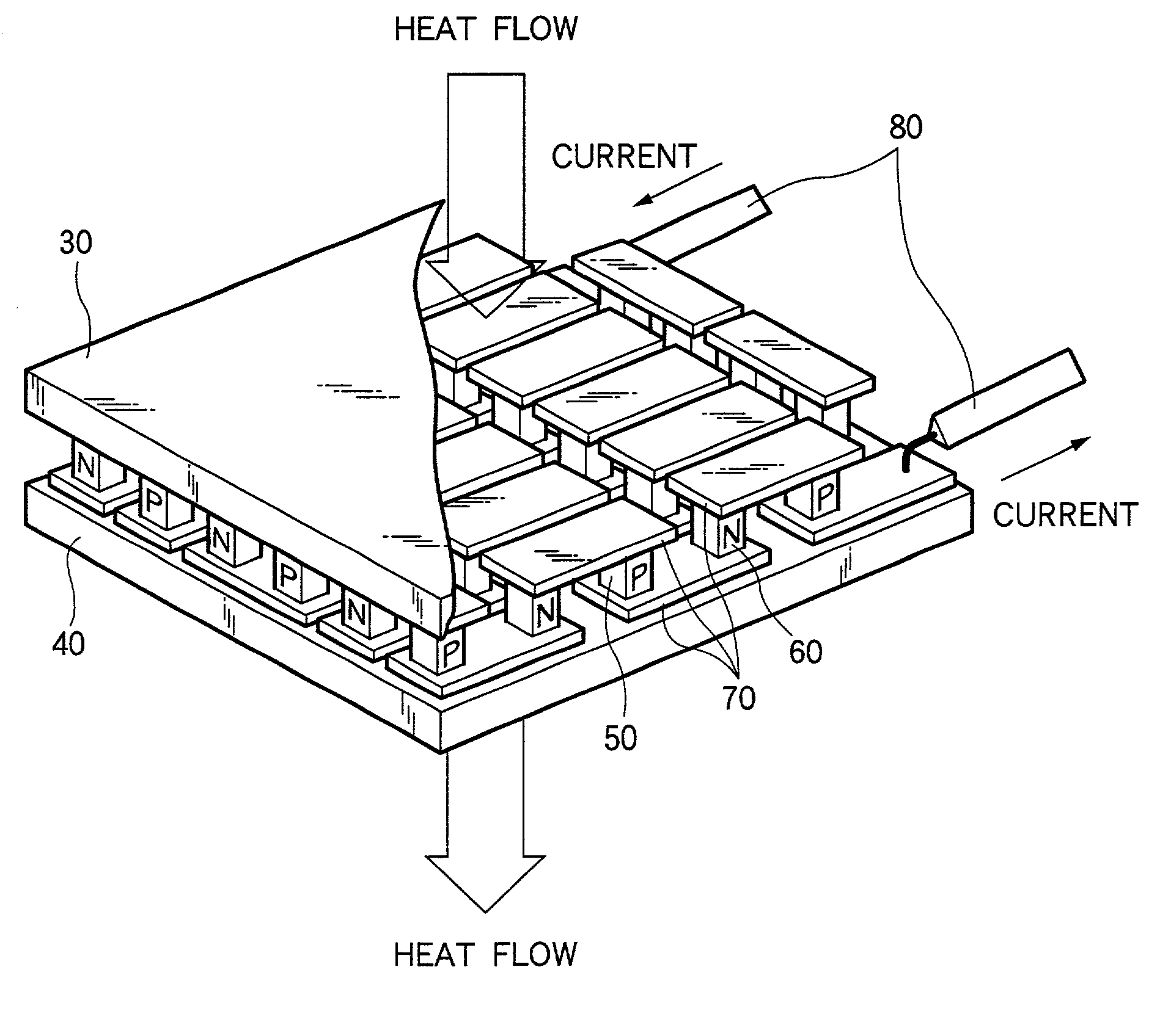
[0032] FIG. 1 illustrates a thermoelectric module according to this invention.

[0033] A thermoelectric module 1 comprises, for example, two ceramic substrates 30 and 40 as heat exchange substrates. A P-type element (P-type semiconductor) 50 and an N-type element (N-type semiconductor) 60 are connected intervention metallic component, for example, an electrode 70 between the two ceramic substrates 30 and 40, to form PN element pair. The metal member includes electrodes made of copper or nickel, a stress relaxation layer, a joining layer or a diffusion layer. For joining the thermoelectric element and the metal member, soldering may be used in a case of a thermoelectric module for low temperature using copper as the metal member but they should be joined, in other cases than described above, by brazing, thermal spraying, solid-state welding (sintering), vapor deposition or mechanical clamping.

[0034] Lead wires 80 are connected to the N-type element at one end of the PN element pair and...

second embodiment

[0076] Then, a second embodiment according to this invention is to be described. In this embodiment, each of N-type and P-type thermoelectric elements is formed as a segment type of a multi-layered structure.

[0077] FIG. 10 shows a thermoelectric module related to this embodiment. FIG. 10 shows an example in which each of N-type and P-type thermoelectric elements has a two layered structure. CoSb.sub.3 with addition of an N-type dopant is used for an N-type thermoelectric element 65 on the high temperature side, and an N-type Bi--Te series compound is used as an N-type thermoelectric element 66 on the low temperature side. On the other hand, an Mn--Si series compound with addition of a P-type dopant is used as a P-type thermoelectric element 55 on the high temperature side and a P-type Bi--Te series compound is used as a P-type thermoelectric element 56 on the low temperature side. When the thermoelectric element on the high temperature side and the thermoelectric element on the low ...

third embodiment

[0080] Then, a third embodiment according to this invention is to be explained. In this embodiment, the unit for the thermoelectric module has a multi-layered structure and is formed into a cascade type.

[0081] FIG. 12 shows a thermoelectric module according to this embodiment. FIG. 12 shows an example in which the unit of the thermoelectric module is constituted as a two layered structure. In the module unit on the high temperature side, CoSb.sub.3 with addition of an N-type dopant is used as an N-type thermoelectric element 67 and an Mn--Si series compound with addition of a P-type dopant is used as a P-type thermoelectric element 57. On the other hand, in the module unit on the low temperature side, an N-type Bi--Te series compound is used as an N-type thermoelectric element 68 and a P-type Bi--Te series compound is used as a P-type thermoelectric element 58. Different materials are used between the high temperature side and the low temperature side because of the same reason as t...


PUM

PropertyMeasurementUnit
temperatureaaaaaaaaaa
thicknessaaaaaaaaaa
thicknessaaaaaaaaaa

Abstract

A thermoelectric module comprising an N-type thermoelectric element having excellent characteristics in atmospheric air even when the temperature rises to a medium-to-high temperature region of about 500° C. and, further, improving the conversion efficiency of a thermoelectric module, by the combination of an excellent P-type thermoelectric material and an excellent n-type thermoelectric material containing a compound having a skutterudite structure, the module comprising an N-type thermoelectric elements each containing a compound having a skutterudite structure, P-type thermoelectric elements each connected directly or by way of a metal member to the N-type thermoelectric elements and containing an Mn-Si series compound,

Description

[0001] 1. Field of the Invention[0002] This invention concerns a thermoelectric module for generating electric power by utilizing the temperature difference and, vice versa, generating temperature difference in accordance with electric power applied.[0003] 2. Description of the Related Art[0004] The thermoelectric module comprises a combination of P-type and N-type thermoelectric elements that utilize thermoelectric effects such as Thomson effect, Peltier effect and Seebeck effect, and includes thermo-couples or electronic cooling elements. Since the thermoelectric module is simple in the structure easy to handle and can maintain stable characteristics, it has been noted for the use in a wide range of applications. Particularly, as the electronic cooling element, since this can conduct local cooling or precision temperature control near the room temperature, research and development have been progressed generally for the application use to temperature control of opto-electronics dev...

Claims


Application Information

Patent Timeline
Patent Type & Authority Applications(United States)
IPC IPC(8): H01L23/38H01L35/20H01L35/22H01L35/34
CPCH01L23/38H01L35/20H01L35/22H01L35/34H01L2924/0002H01L2924/00H10N10/854H10N10/855H10N10/01
Inventor HARA, REIKOAOYAMA, IKUTOTOMITA, KENICHIISHIDA, KOUICHI
Owner KOMATSU LTD
Why Eureka
Try Eureka