Projection optical system and projection exposure apparatus

a technology of projection optical system and exposure apparatus, which is applied in the direction of photomechanical apparatus, instruments, lenses, etc., can solve the problems of difficult to achieve chromatic aberration correction, limited use of lens materials, thermal aberration,

Inactive Publication Date: 2002-02-28
CANON KK
View PDF8 Cites 128 Cited by
  • Summary
  • Abstract
  • Description
  • Claims
  • Application Information

AI Technical Summary

Problems solved by technology

However, as the exposure wavelength reaches a region of 193 nm (ArF excimer laser light) or 157 nm (F.sub.2 excimer laser light), usable lens materials are limited to quartz and fluorite.
Also, due to thermal absorption by lenses, there occur problems (thermal aberration) such as changes of aberration or shift of the focal point position.
However, because the difference in dispersion between them is not large, correction of chromatic aberration is difficult to accomplish.
This leads to an increase of the total glass material thickness of the optical system, which then raises the above-described problems of thermal aberration and transmission factor.
Further, currently, it is very difficult to produce a projection optical system by use of fluorite, having a sufficient property to assure its design performance.
It is further difficult to produce one having a large diameter.
This makes it very difficult to accomplish color correction, and results in an increase of the cost.
The chromatic aberration can not be corrected only with a single lens material Any way, it is very difficult to provide a projection optical system only by use of dioptric systems.
This optical system has inconveniences that, in every picture angle used, there occurs light interception (void) at the central portion of a pupil and that the exposure region can not be made large.
If the exposure region is to be enlarged, it disadvantageously causes widening of the light interception at the central portion of the pupil.
In the projection optical systems shown in Japanese Laid-Open Patent Applications, Laid-Open Nos. 211332 / 1997 and 90602 / 1998, the basic structure comprises a reflection system only However, in respect to aberration (Petzval sum) and mirror disposition, it is difficult to keep sufficient imaging region width on the image plane.
Also, since in this structure a concave mirror adjacent the image plane and having a large power mainly has an imaging function, enlargement of NA is difficult to accomplish.
Since a convex mirror is placed just before the concave mirror, a sufficient image-side working distance can not be maintained.
This causes enlargement of the incidence and reflection angles of the mirror Further, an enlarged NA (numerical aperture) will cause a large increase of the mirror diameter.
In the projection optical systems shown in Japanese Laid-Open Patent Applications, Laid-Open Nos. 163319 / 1988, 188298 / 1993 and 230287 / 1994, the structure is complicated due to deflection and bend of the optical path.
Since most of the power of optical groups for imaging an intermediate image, as a final image, is sustained by a concave mirror, it is structurally difficult to enlarge the NA.
Because of it, a sufficient image-side working distance can not be kept.
As the exposure wavelength is shorted to 157 nm, this is undesirable also in respect to the loss of light quantity.
Further, it is structurally difficult to hold the imaging region width because of the necessity of light path division.
Since the optical system has to be large, there is a disadvantage in respect to the footprint.
In the projection optical systems shown in Japanese Laid-Open Patent Applications, Laid-Open Nos. 66510 / 1990 and 282527 / 1991, the optical path is divided by a beam splitter, and this makes the barrel structure complicated.
It needs a beam splitter of large diameter and, if this is of a prism type, the loss of light quantity is large because of its thickness.
Further, there may occur aberrations due to a change in characteristic at the light dividing surface or production of asymmetric aberration resulting from thermal absorption.
It is therefore difficult to manufacture the beam splitter very accurately.
This requires eccentric optical handling and it makes the structure and assembling very complicated.

Method used


Image

  • Projection optical system and projection exposure apparatus
  • Projection optical system and projection exposure apparatus
  • Projection optical system and projection exposure apparatus

Examples


second embodiment

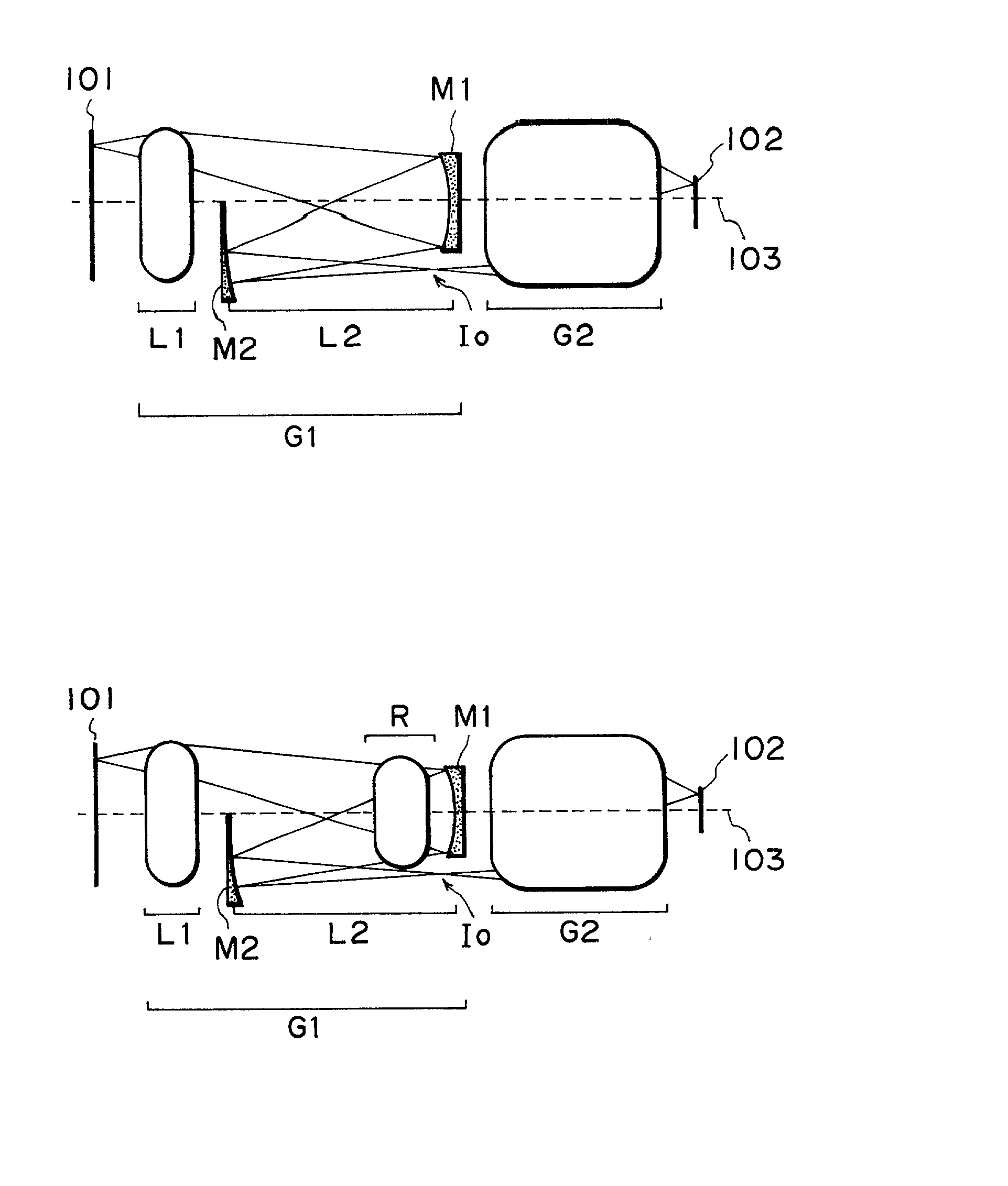
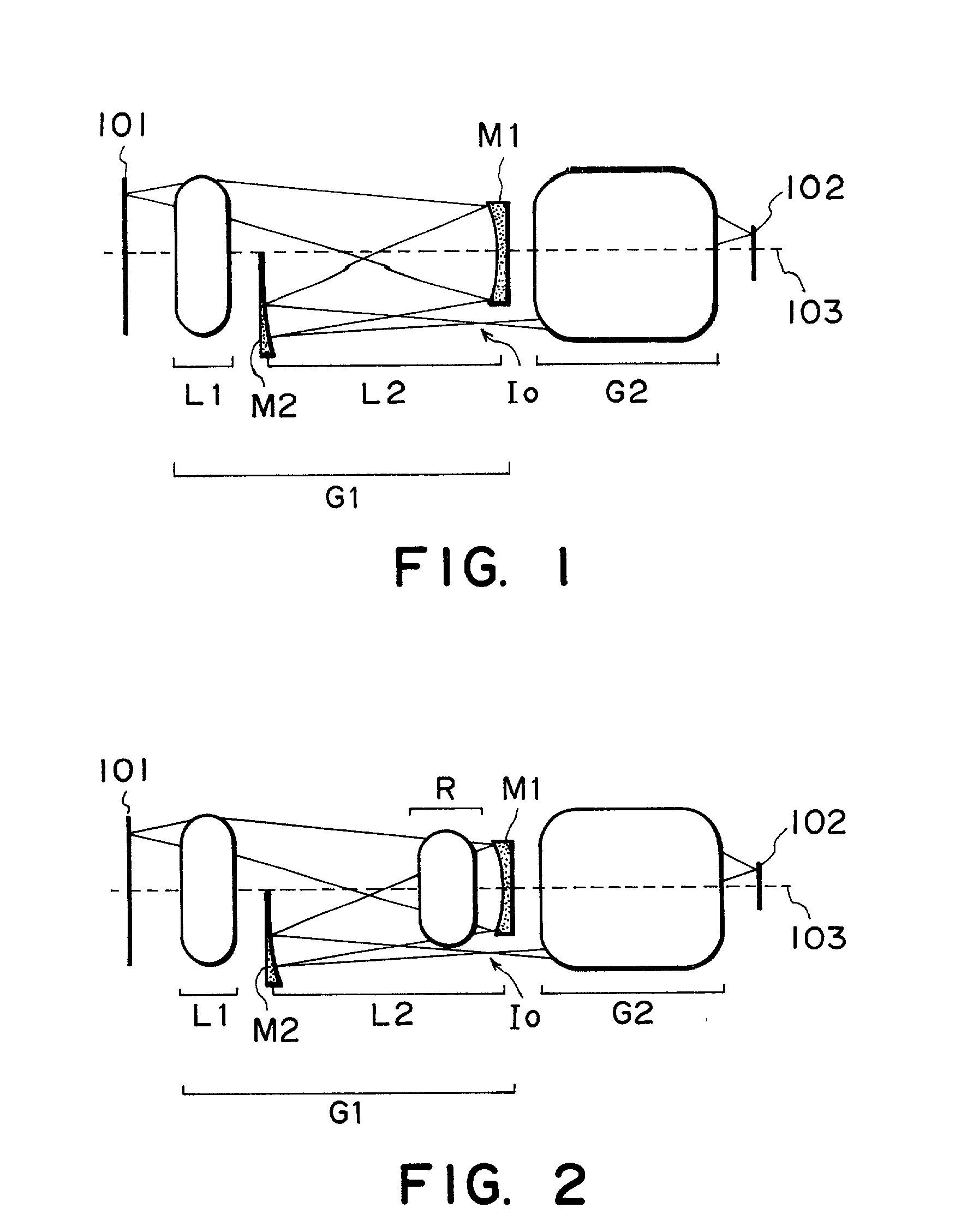
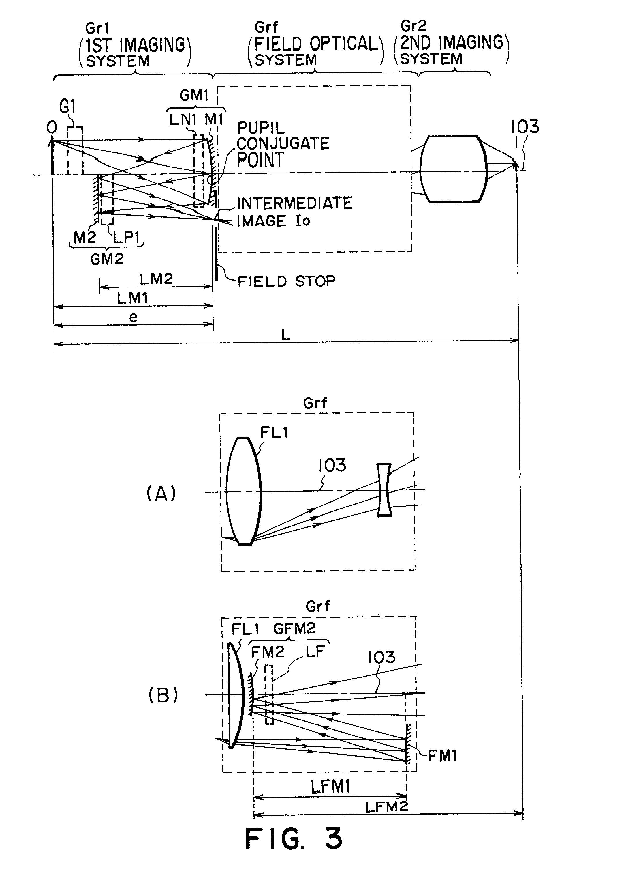
, respectively, to which the second embodiment is applied, to be described later. In all examples, the first imaging system Gr1 has two mirrors, and the second imaging system Gr2 comprises refractive lens systems only FIGS. 12-19 shows cases wherein the field optical system Grf is all provided by lens systems, and FIGS. 20-28 show cases wherein the field optical system Grf has two mirrors.

[0119] Generally, where a mirror is used, the optical system functions as follows.

[0120] (a) No chromatic aberration occurs at the mirror.

[0121] With this feature, when a concave lens and a concave mirror are combined to provide a Mangin mirror, even by a positive power, excessive dichromatism can be produced.

[0122] (b) The relation between the power of the mirror and the Petzval sum is opposite to that of an ordinary refractive lens.

[0123] With this feature, since a concave mirror, for example, has a negative value of Petzval sum while it has a positive power, the power load of a negative lens in ...

example 1

[0165] FIG. 4 shows a specific lens structure of Example 1. The projection magnification was 1:4, and the design base wavelength was 157 nm. The glass material was fluorite.

[0166] The projection optical system comprises, in an order from the object side, a refractive lens group L1 having a positive refracting power, a refractive lens group R which is a reciprocal optical system wherein both the incidence light and reflection light of a first mirror M1 (to be placed later) transmit therethrough, a concave mirror (first mirror) M1, a concave mirror (second mirror) M2, a field lens group F, and a second imaging optical system G2.

[0167] In this embodiment, the image side numerical aperture was NA=0.6, the reduction magnification was 1:4, and the object-to-image distance (from the first object plane to the second object plane) was L=about 1170 mm. The design base wavelength was 157 nm. In the range of the image height of about 11.25-19.75 mm, the aberration was corrected. An abaxial expo...

example 2

[0175] FIG. 5 shows a specific lens structure of Example 2. The projection magnification was 1:4, and the design base wavelength was 157 nm. The glass material was fluorite.

[0176] The projection optical system comprises, in an order from the object side, a refractive lens group L1 having a positive refracting power, a refractive lens group R which is a reciprocal optical system wherein both the incidence light and reflection light of a first mirror M1 (to be placed later) transmit therethrough, a concave mirror (first mirror) M1, a flat mirror (second mirror) M2, a field lens group F, and a second imaging optical system G2.

[0177] In this embodiment, the image side numerical aperture was NA=0.60, the reduction magnification was 1:4, and the object-to-image distance (from the first object plane to the second object plane) was L=about 1205 mm. In the range of the image height of about 10-16.25 mm, the aberration was corrected. An abaxial exposure region of arcuate shape, having at leas...


PUM

PropertyMeasurementUnit
exposure wavelengthaaaaaaaaaa
wavelengthaaaaaaaaaa
distanceaaaaaaaaaa

Abstract

Disclosed is a projection optical system for projecting an image of an object onto an image plane, which includes a first imaging optical system for forming an image of the object, a second imaging optical system for re-imaging the image upon the image plane, wherein the first and second imaging optical systems are disposed in an order from the object side and are disposed along a common straight optical axis, wherein the first imaging optical system includes a first mirror for reflecting and collecting abaxial light from the object, wherein one of the first and second imaging optical systems includes a second mirror for reflecting light from the first mirror to the image plane side, and wherein, with the second mirror, the abaxial light is caused to pass an outside of an effective diameter of the first mirror.

Description

FIELD OF THE INVENTION AND RELATED ART[0001] This invention relates to a projection optical system and a projection exposure apparatus for projecting a pattern of a mask onto a substrate through the projection optical system. More particularly, the invention concerns a catadioptric projection optical system having a reflection mirror, for printing, by projection exposure, a reticle pattern oil a semiconductor wafer.[0002] The density of an integrated circuit increases more and more, and the specification and performance required for a projection (exposure) optical system become much strict. Generally, in order to obtain a higher resolving power, the exposure wavelength is shortened and / or the numerical aperture (NA) of a projection optical system is enlarged.[0003] However, as the exposure wavelength reaches a region of 193 nm (ArF excimer laser light) or 157 nm (F.sub.2 excimer laser light), usable lens materials are limited to quartz and fluorite. This is mainly because of decreas...

Claims


Application Information

Patent Timeline
Patent Type & Authority Applications(United States)
IPC IPC(8): G02B13/18G02B17/08G03F7/20H01L21/027
CPCG02B13/143G02B13/24G02B17/0621G02B17/0812G02B17/0844G02B17/0852G02B17/0856G02B17/0892G03F7/70225G03F7/70275
Inventor TERASAWA, CHIAKIISHII, HIROYUKIKATO, TAKASHI
Owner CANON KK
Why Eureka
Try Eureka