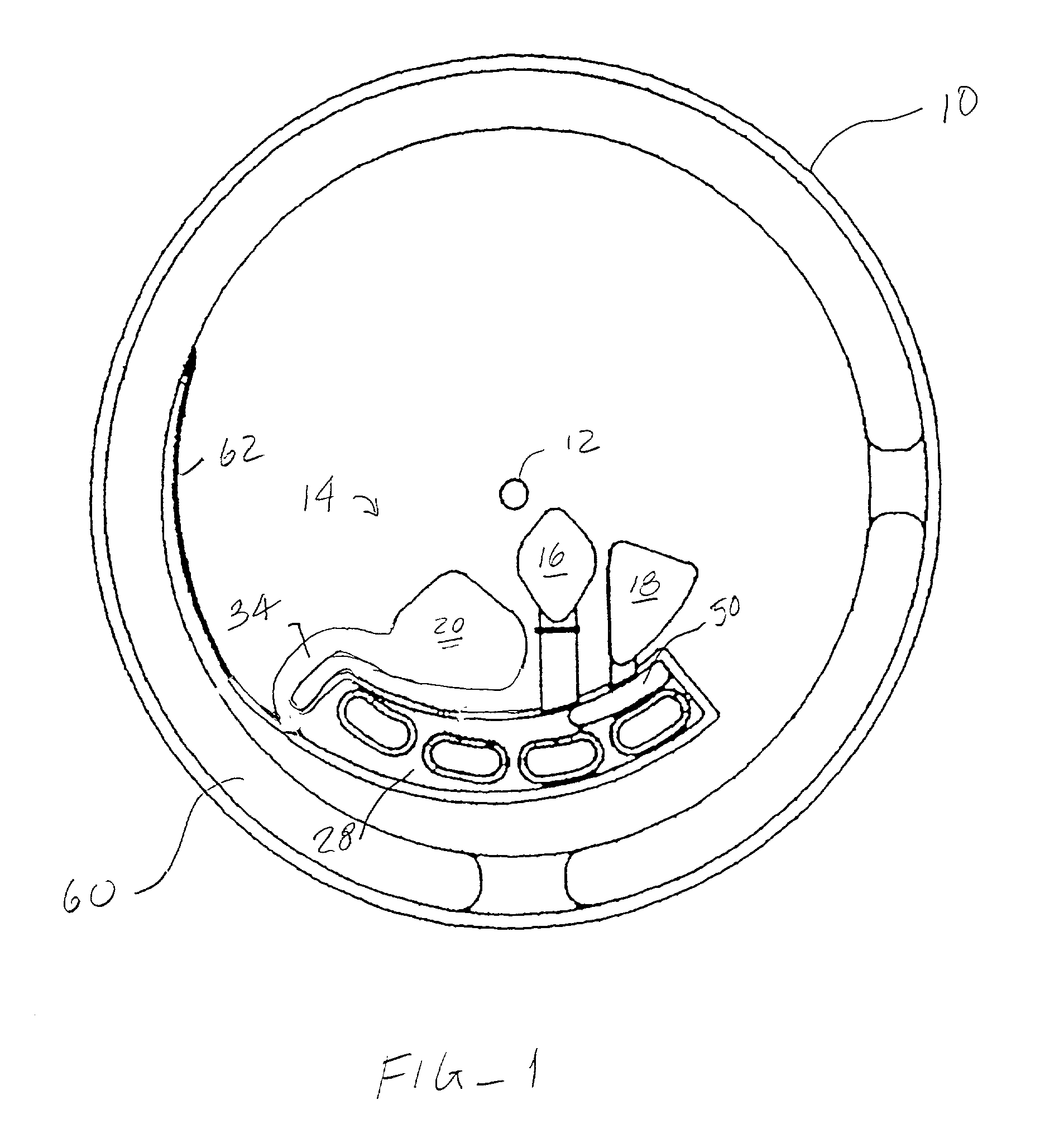
[0011] An analytical rotor constructed in accordance with the principles of the present invention comprises a rotor body having a
coupling element which defines an axis of rotation. The
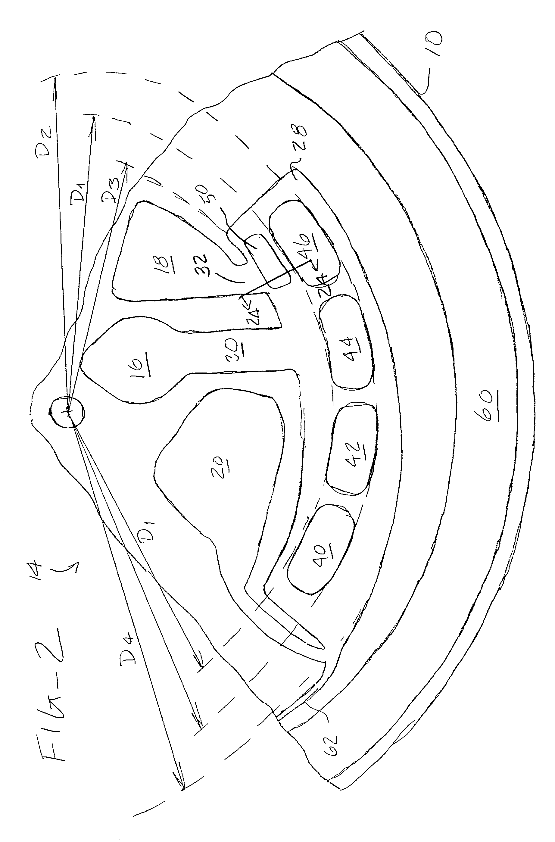
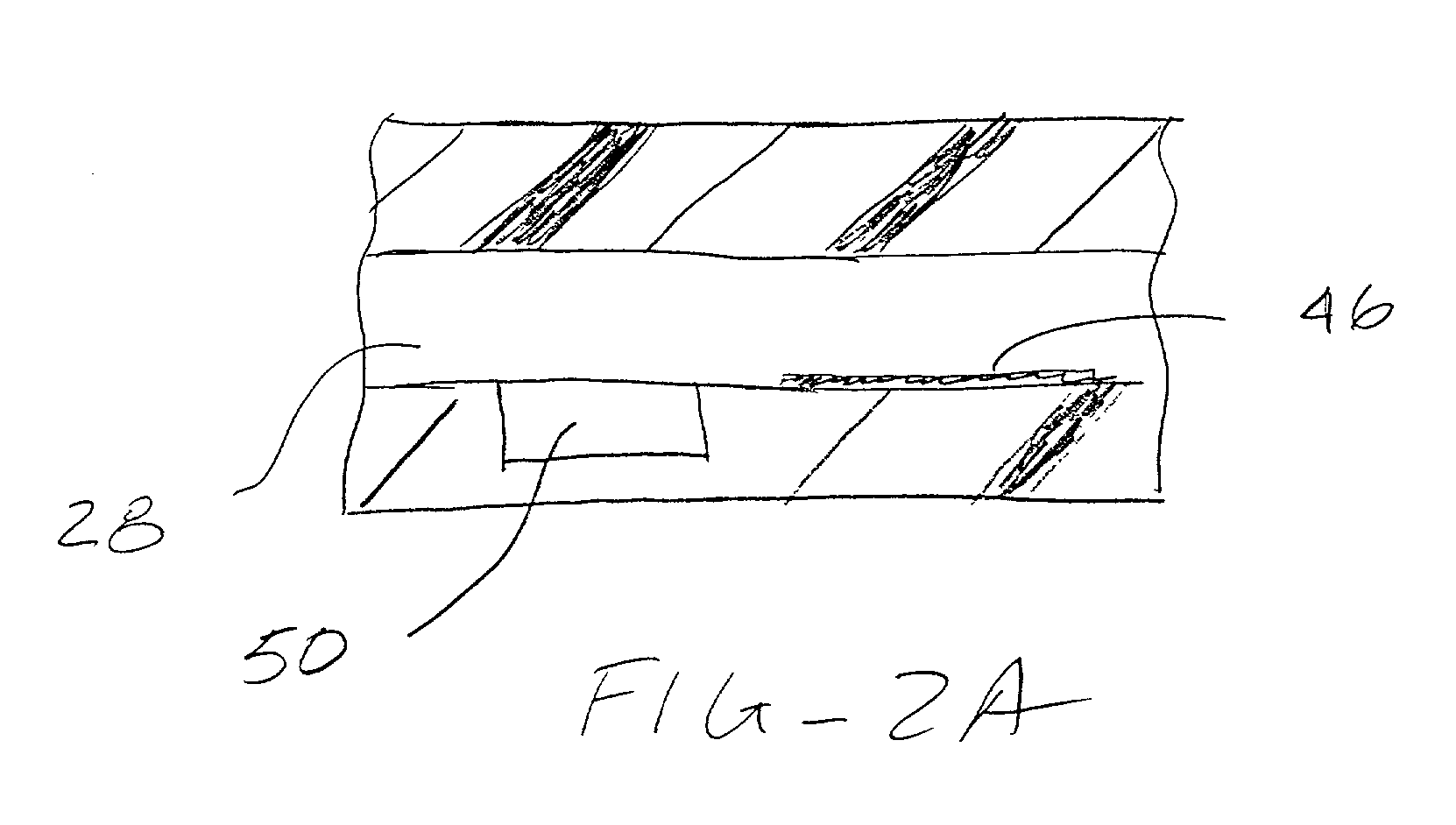
coupling element is typically a receptacle for receiving the spindle of a rotor, but could be any device or mechanism which permits detachable mounting of the rotor on a centrifugal drive unit. The rotor body includes an inlet chamber having a sample application port which permits introduction of liquid sample from an external dispenser. The rotor body further includes a reaction chamber disposed radially outwardly from the inlet chamber and a collection chamber disposed radially outward from the reaction chamber. Flow control among the chambers is achieved by connecting the reaction chamber to receive liquid flow from the inlet chamber by a first flow path in the rotor body, where the first flow path has a flow resistance selected to pass liquid at a first rate of rotation of the rotor body, typically being a low rate in the range of 100 rpm to 1000 rpm, usually 300 rpm to 900 rpm. The collection chamber is positioned to receive liquid flow from the reaction chamber by a second flow path having a much higher flow resistance selected to substantially inhibit liquid flow at the first rate of rotation. Flow through the second flow path (and emptying of the reaction chamber to the collection chamber) can be achieved at a second rate of rotation greater than the first rate of rotation, typically by a factor of at least about four. Usually, the first flow path will have a relatively large cross-sectional area, typically being greater than 0.5 mm.sup.2, and a relatively
short length, typically being less than 5 mm. In contrast, the second flow path has a relatively small cross-sectional area, typically less than 0.1 mm.sup.2, and a much greater length, typically more than 25 mm. Additionally, the second flow path can be directed along a spiral or other non-direct (i.e., nonradial) path from the reaction chamber to the collection chamber to further enhance resistance. In this way, substantially no overflow from the reaction chamber to the collection chamber occurs during the first rotation at the first rotational speed, while the reaction chamber can be quickly emptied by the second rotation at the much higher
rotational rate.
[0012] In the exemplary embodiment, the analytical rotor further includes a wash chamber disposed radially inwardly from the reaction chamber, where the wash chamber has a wash application port and is connected to the reaction chamber by a third flow path having a flow resistance selected to pass wash liquid at the first rate of rotation. The exemplary analytical rotor also includes a
label chamber disposed radially inwardly from the reaction chamber. The
label chamber includes a
label application port (which may receive a label-containing fluid, or which may receive a fluid which does not contain label but which rehydrates dry label
reagent within the label chamber) and is connected to the reaction chamber by a fourth flow path having a flow resistance selected to pass
labelling reagent liquid at the first rate of rotation. In this way,
plasma, wash liquids, and labels and other reagents can be selectively introduced from their respective chambers into the reaction chamber without significant overflow or loss of these liquids into the collection chamber. Each of these liquids, however, can be readily and selectively transferred into the collection chamber simply by rotating the rotor at the second
rotational rate.
[0013] Usually, the reaction chamber will include at least one discrete
reaction zone comprising an immobilized specific binding substance on a wall or other
solid phase therein. Usually, the reaction chamber will include at least two discrete reaction zones, and more usually will include three or more discrete reaction zones. In this way, multiple analytes can be detected simultaneously in small volumes of patient
plasma.
[0014] In a specific aspect of the present invention, a vapor collection region will be provided within the reaction chamber. The vapor collection region will be spaced radially inward from the reaction zones(s) and will preferably have a depressed "lower" surface so that air and other gases present in the chamber will move to this region as the rotor is rotated at the first rate of speed. In this way, the liquid sample and other reagents will cover the
reaction zone(s) without discontinuities caused by vapor pockets. The region is preferably disposed at the innermost end of a radially tapered inward wall.
[0015] In another specific aspect of the apparatus of the present invention, at least a portion of the inner walls of the chambers and flow paths of the analytical rotor will be hydrophobic. In particular, hydrophobic wall portions within the reaction chamber may enhance the rate of
protein binding (via adsorption) and decrease the
desorption of proteins during the
assay protocols. More importantly,
hydrophobic surfaces within the flow paths further decrease the likelihood of overflow and fluid
capillary action which might cause accidental fluid transfer when the rotor is not being rotated. That is, the
hydrophobic surfaces greatly decrease the likelihood that liquid would enter any of the flow paths in the absence of outwardly radial forces generated by the rotation of the rotor body. Further, hydrophobic surfaces within the sample application chamber facilitate the movement, venting, and collection of air during liquid filling and transfer operations.
[0018] The rotor and method of the present invention provide particularly advantageous techniques for filling the inlet chambers with sample, diluents, and other reagents. The inlet chambers may be precisely dimensioned so that, when filled to a predetermined level or point, there is an exact quantity of liquid transferred to the rotor. The use of hydrophobic surfaces, as described above, further assures that the chamber(s) will be completely filled. Filling may be accomplished using a transfer pump and a fill detection apparatus, such as a
refractive index detector. When fluid is filled to any predefined point, usually a location within the
low resistance flow path connecting the inlet chamber to the reaction chamber, flow is immediately stopped. Alternatively, the rotor and methods of the present invention could rely on the transfer of premeasured quantities of sample and / or other reagents, in which case the volume of the inlet chamber(s) would be less critical.

