
Rotation direction detector in ignition equipment of an internal combustion engine

a technology of rotation direction and detector, which is applied in the direction of engine ignition, indication/recording movement, other installations, etc., can solve the problems that known relationships have not been generated or used specifically, and achieve the effects of reducing circuitry and/or programming requirements, reducing angular range, and increasing speed and dynamic respons

Inactive Publication Date: 2002-06-27
PRUFREX ELECTRO APPBAU INH HELGA MULLER GEBR DUTSCHKE
View PDF17 Cites 13 Cited by
  • Summary
  • Abstract
  • Description
  • Claims
  • Application Information

AI Technical Summary

Benefits of technology

[0009] The object of the invention is to create a direction of rotation recognition system, suitable for an internal combustion ignition system, which renders possible ascertainment of the direction of rotation with a minimal angular range with a greater speed and dynamic response and a reduced circuitry and / or programming requirement. In particular, the result of the recognition of the direction of rotation is to be fixed in respect of angle, i.e., always available in the same rotational position of the magnet wheel.
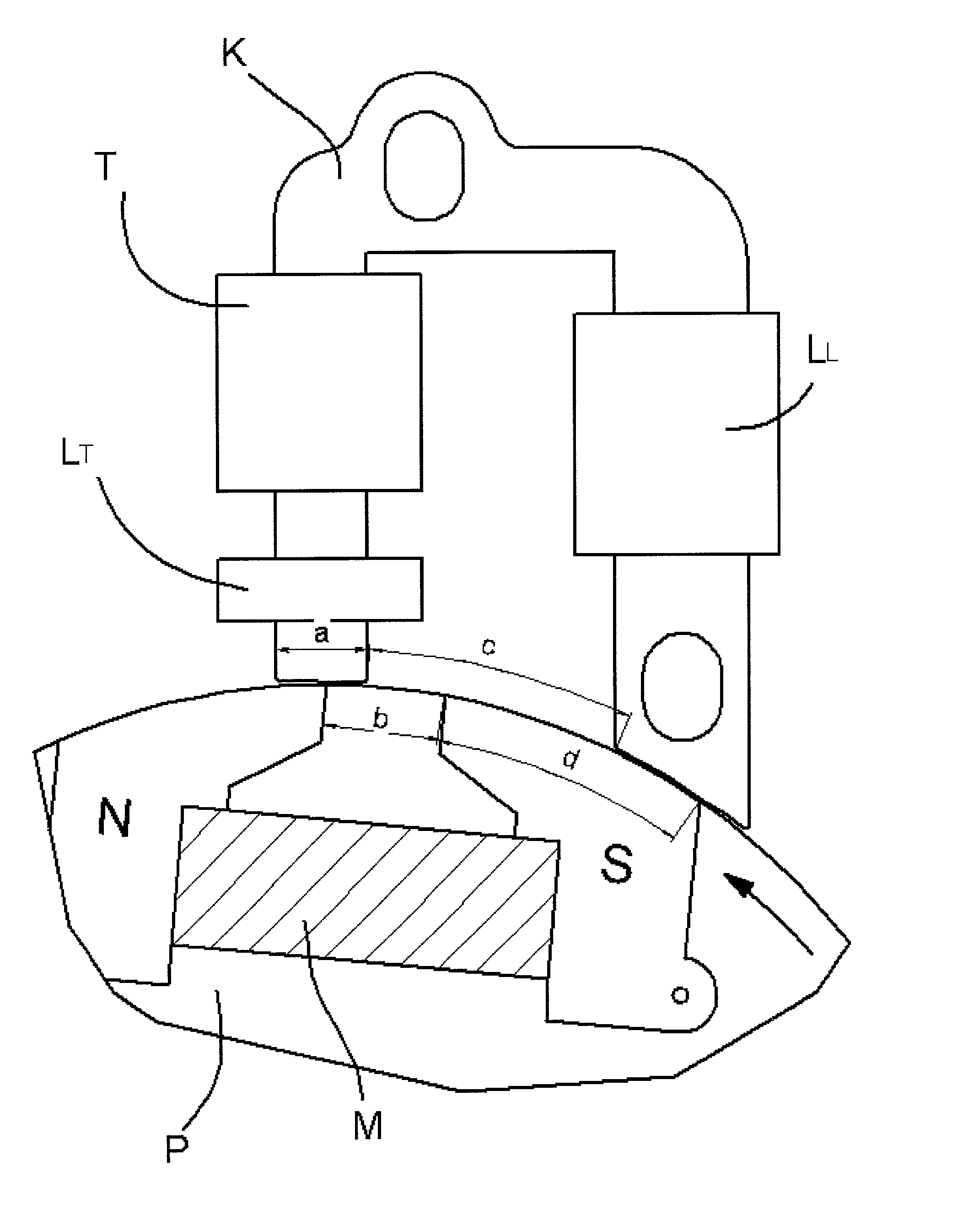
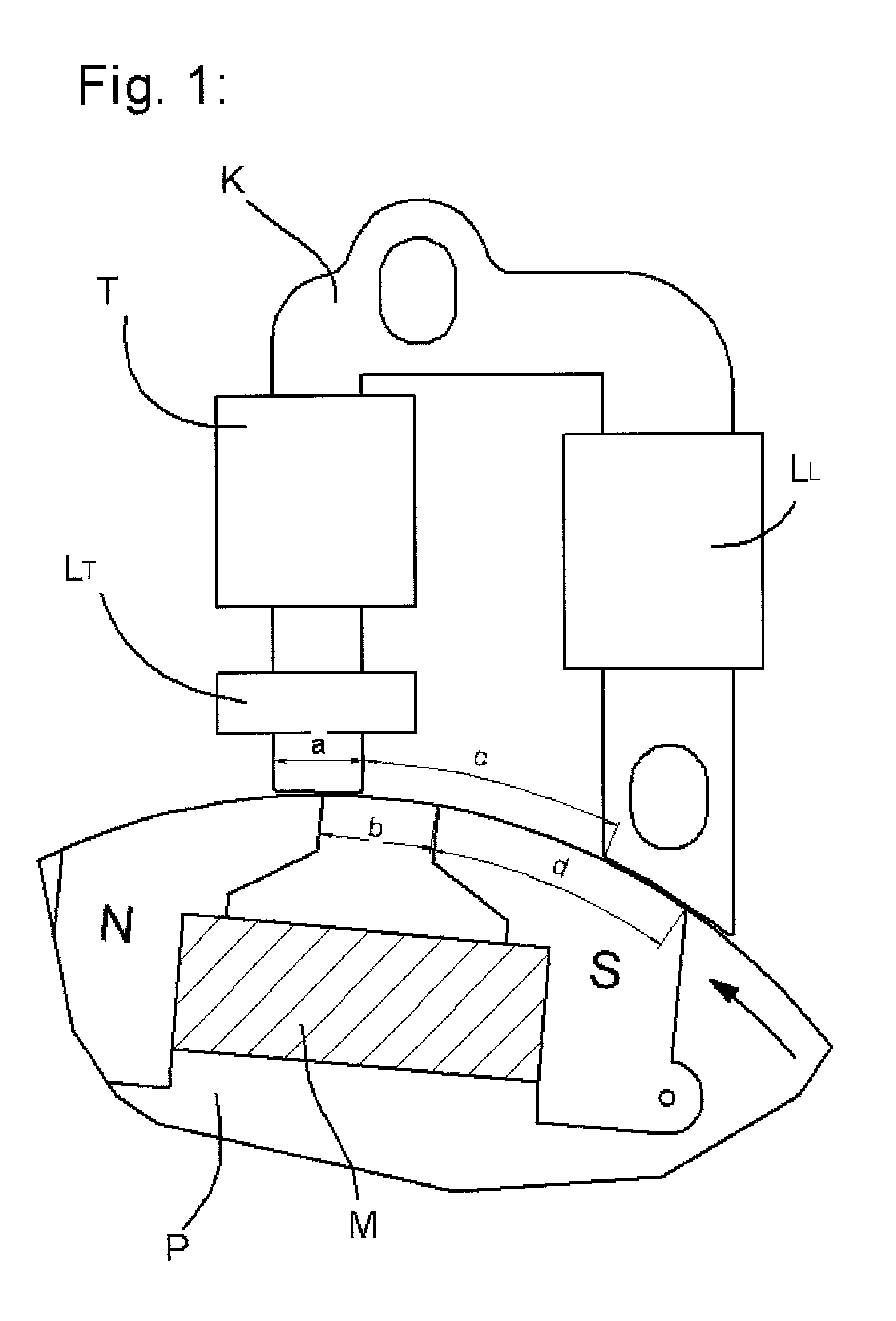
[0016] In particular, the inventive concept consists in recognition of the direction of rotation from the voltage characteristic within a half-wave or a voltage pulse on the basis of the indicative point such as, for example, dip, minimum in the amplitude peak range or other discontinuity points. Ignition coil arrangements with a U-shaped iron core whose two limbs are directed towards the circumference of the magnet wheel are used in many cases. For each revolution, this generates a voltage pulse with three half-waves of alternating polarity. According to an advantageous development of the invention, in the case of an ignition coil arrangement with a U-shaped iron core, the middle half-wave is used to contain the information on the direction of rotation in the form of the indicative discontinuity point or extreme point, including a voltage dip. The preceding and succeeding voltage half-waves of opposite polarity can therefore be removed, in particular, filtered out, by the evaluation means, so that the middle half-wave can be evaluated independently of the preceding or the succeeding half-wave. This achieves the advantage that only a very small angular range, of the order of magnitude of one degree, need be evaluated for the purpose of recognition of the direction of rotation.
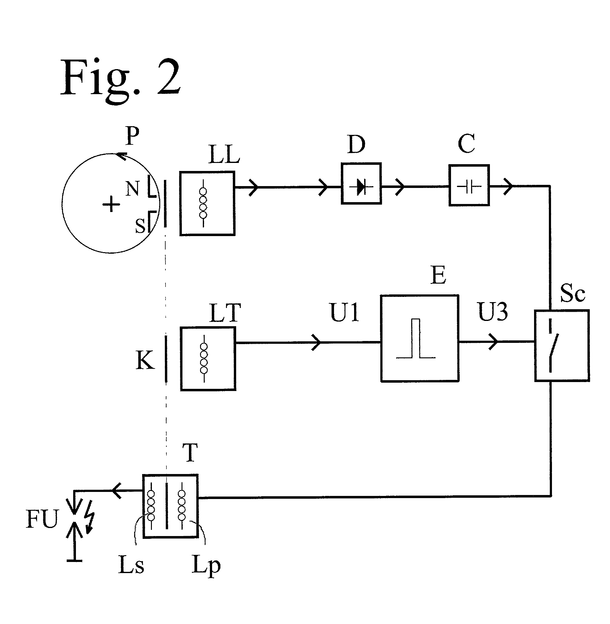
[0017] A further advantage of the general inventive concept consists in the fact that it can be realized by means of discrete circuit technology with a CR differentiating device and simply constructed transistor switching elements, the latter, in particular, for realization of the output signal generator. With this technology, the voltage half-wave with the indicative point (voltage dip, break point, etc.) can be advantageously utilized as a supply voltage for the active components, such as transistor switches, in the differentiating device. Since this half-wave with the information on the direction of rotation must always have a determined polarity (for correct direction of rotation), the output signal generator is consequently activated only if the direction of rotation is correct. In this way, a direction of rotation signal can be generated with high reliability and a small circuitry requirement.

Problems solved by technology

Hitherto, however, these known relationships have not been generated or used specifically for the purpose of recognizing direction of rotation.

Method used


Image

  • Rotation direction detector in ignition equipment of an internal combustion engine
  • Rotation direction detector in ignition equipment of an internal combustion engine
  • Rotation direction detector in ignition equipment of an internal combustion engine

Examples


Embodiment Construction

[0024] The ignition system according to the invention is based on a magnet generator which, as shown by FIG. 1, comprises a magnet wheel P, disposed in a torsionally rigid manner on the crankshaft of an internal combustion engine, not depicted, with a peripherally disposed magnet M. The direction of rotation is indicated by an arrow pointing anti-clockwise. A pole shoe N, S is respectively mounted on the north- and south-pole ends of the magnet M. With each revolution of the magnet wheel P, this magnet arrangement M, N, S is moved past an iron yoke core K with two limbs. The magnetic circuit can thus close once with each revolution, when the two limbs of the iron yoke core K each lie at least partially opposite one of the two pole shoes N, S. The limb which lies opposite the north pole N when the magnetic circuit is closed is encompassed by the ignition transformer T and by the trigger coil LT, whereas the other limb, lying opposite the south pole S, is surrounded by a charging coil...


PUM


Abstract

Apparatus and method for detecting the direction of rotation of an internal combustion engine using a magnet wheel which moves past an electrical ignition coil. For each revolution, at least one current or voltage pulse is induced in the coil having a polarity dependent on the direction of rotation. The magnet poles and the coil have geometric relationships that, upon each magnet wheel revolution, the curve form of the current or voltage pulse has at least two prespecified extreme points with a curve characteristic which is substantially neither rising nor falling and at least one break point with a discontinuity. A direction of rotation signal is derived from these curve characteristics.

Description

(e) BACKGROUND OF THE INVENTION[0001] 1. Field Of The Invention[0002] The invention concerns a method for recognition of direction of rotation for the ignition system of an internal combustion engine using a magnet wheel which can be moved past an electrical ignition coil arrangement by the internal combustion engine. As a result, there is induced in the coil arrangement, for each revolution, at least one current pulse or voltage pulse whose polarity is dependent on the direction of rotation. The invention further concerns an ignition module with (electronic) evaluation means for recognition of direction of rotation according to the aforementioned method. In this case, the evaluation means perform sampling, evaluation and / or processing of current pulses or voltage pulses which have been induced by interaction with the rotating magnet wheel. The invention further concerns a direction of rotation detector, suitable for use in the said method or ignition module, whose input can be coup...

Claims


Application Information

Patent Timeline
Patent Type & Authority Applications(United States)
IPC IPC(8): F02D41/34F02P7/067F02P11/02G01D5/20G01P13/04
CPCF02D41/009F02D2250/06F02D2400/06G01P13/045F02P11/02G01D5/2033G01P13/04F02P7/0675
Inventor KIESSLING, LEO
Owner PRUFREX ELECTRO APPBAU INH HELGA MULLER GEBR DUTSCHKE
Learn More