Hybrid electro-optic cable

a hybrid cable and optical communication technology, applied in the direction of cables, flat/ribbon cables, instruments, etc., can solve the problems of pstn carrying the triple burden of voice, fax, data communication, and severely limited transmission bandwidth to a telephone subscriber, and achieves reduced initial system cost and ongoing maintenance costs, and significant savings for users/clients

Inactive Publication Date: 2002-09-12
SEAFORT INT TRADING SRL
View PDF7 Cites 267 Cited by
  • Summary
  • Abstract
  • Description
  • Claims
  • Application Information

AI Technical Summary

Benefits of technology

0047] The present invention further comprises various communication system embodiments which involve the separation of an indoor optoelectronics module (or package) from an outdoor optical antenna unit. This approach provides significant benefits to the small and medium size business market in terms of scalability, reliability, and costs of installation and maintenance.
0048] In one set of embodiments, a wireless optical transceiver system includes an optical antenna unit coupled via hybrid cable to an optoelectronics module. The transceiver system receives and transmits light beams from / to the atmosphere, and thereby communicates optically with a second optical transceiver. The isolation between the optoelectronics module and optical antenna unit provided by the hybrid cable has a host of implications which reduce the initial system cost and ongoing maintenance costs to the user. In particular, the optical antenna unit, free from the encumbering influence of optoelectronic system components, may be installed more easily and efficiently. Line of sight to a target antenna may be achieved by disconnecting the hybrid cable from the optical antenna and visually observing through the optical path of the optical antenna. Furthermore, the isolation implies that a utility power connection is not needed at the site of the optical antenna. This results in significant savings to the user / client.
0049] In addition to an optical transceiver system, the present invention also contemplates receivers, transmitters, repeaters, switches and routers, or any combination thereof configured according to the principle of hybrid cable isolation between optical antenna units and optoelectronics modules. Such components are admirably suited for use in various network configurations such as broadcast networks, bi-directional communication networks, point-to-multipoint networks, point-to-point links, etc. due to their low cost, ease of installation and antenna sighting, modularity, and upgradability.

Problems solved by technology

Thus, the transmission bandwidth deliverable to a telephone subscriber is severely limited, typically not more than 56,600 bits per second.
At present, the PSTN bears the triple burden of conveying voice, fax, and data communications, and is nearly saturated in certain large metropolitan regions.
First time subscribers to ISDN service generally incur a cost for installation of an ISDN line which comprises upgraded copper wire.
Thus, the cost of implementing a fiber optic network may be exorbitant.
In general, hard-wired networks are burdened with the requirement of laying cable to new subscribers / nodes.
Furthermore, it is difficult to reconfigure the topology of an existing hard-wired network since cables are quite often buried underground, suspended from poles, or strung through the interstitial spaces of office buildings.
Thus, the radio spectrum is increasingly crowded, resulting in degraded signal quality and / or increased subscriber costs.
Thus, the transceiver enclosure is often large (in size) and massive.
In addition, the transceiver enclosure is power hungry because of the active electronics, network interface and environment control system, and thus, may require the installation of a special power utility connection at the outdoor location.
It is noted however that there may be significant difficulty in obtaining outdoor (especially rooftop) electrical utility access, and the conditioning and reliability of rooftop power connections is often found lacking.
Potential home and small business customers may be unwilling to pay for the costs associated with installing an outdoor electrical utility connection.
However, the mass of the transceiver enclosure and its associated mounting structures may create roof loading problems.
The problem of stably mounting the transceiver enclosure is a nontrivial one due to the significant weight and volume of the transceiver enclosure.
Newer roof membrane systems often disallow the use of penetration type mounts, and aesthetic or zoning requirements may exclude parapet-mounted devices.
Thus, a large tripod, besides occupying valuable roof space, can create (or exacerbate) roof loading problems.
The difficulty in obtaining stability of the transceiver enclosure usually necessitates the incorporation of an active-alignment system to continuously monitor and correct the fine pointing of the antenna optics to maintain the line-of-sight to the other FSO transceiver.
The active alignment system adds significant cost and weight to an already complex system.
The spotting scope is needed because the typical transceiver enclosure provides no convenient means for intercepting the optical path of the transmit and receive beams.
Alignment is often a painstaking and tedious task, requiring many iterations of adjustment between the two communicating transceivers.
Furthermore, significant costs may be incurred as one or more trained persons may be required to perform the alignment.
FSO transceiver systems rarely address the need for scalability.
In addition, any repair of an FSO transceiver typically requires the complete replacement and realignment of the transceiver enclosure, which can result in unacceptable downtime.
A major portion of the cost of typical FSO communication systems is due to their use of six optoelectronic (OE) interfaces to complete a single point-to-point link as suggested by FIG. 2.
The use of six OE interfaces adds significantly to the installed cost of the point-to-point link as the bandwidth is increased.
The aforementioned problems associated with typical free-space optical data communication systems have often relegated point-to-point FSO systems to the niche markets.

Method used


Image

  • Hybrid electro-optic cable
  • Hybrid electro-optic cable
  • Hybrid electro-optic cable

Examples


second embodiment

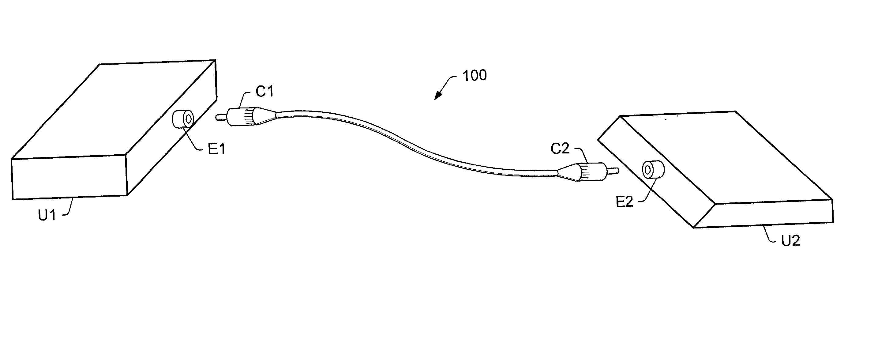
[0176] In a second embodiment, hybrid cable 960 is replaced by hybrid cable 100 and a separate insulated electrical wire. The two electrically conductive connections are provided by conductive strands in hybrid cable 100 and the separate insulated electrical wire.

third embodiment

[0177] In a third embodiment, hybrid cable 960 is replaced with hybrid cable 600. The two simplex units in hybrid cable 600 each contribute one electrically conductive connection. The optical fiber in one simplex unit carries the bi-directional light traffic while the optical fiber in the other simplex unit may be unused. Equivalently, two of hybrid cable 100 may substitute for hybrid cable 600.

[0178] In another set of embodiments, an optoelectronics module may be configured as a transmit-only device. Thus, the optical receiver 722 may be omitted from optoelectronics module OEM, and the optical antenna unit OAU may be configured with only one lens cone. At least one hybrid cable couples the optoelectronics module and optical antenna unit to provide a fiber optic path for the transmit light beam. As with the bi-directional transceiver embodiments described above, a variety of connectivity options are available for providing the two electrical connections in support of the safety cont...


PUM

PropertyMeasurementUnit
mean time before failureaaaaaaaaaa
lengthaaaaaaaaaa
field of viewaaaaaaaaaa

Abstract

A hybrid cable comprising an optical fiber, an intermediate layer surrounding the optical fiber, and an electrically insulating jacket surrounding the intermediate layer. The intermediate layers include a collection of metallic strands. The hybrid cable may be used to establish simultaneous electrical and fiber-optic connection between two communication devices. Thus, the two communication devices may simultaneously transfer optical signals through the optical fiber and perform any of various electrical functions (power transfer, eye safety control) through the metallic strands. For example, an optical transceiver may couple to an optical antenna unit through the hybrid cable. Such an optical transceiver may serve as part of a point-to-point link, a point-to-multipoint link, and/or, a link between a primary transceiver unit and an optical router.

Description

CONTINUATION DATA[0001] This application is a continuation in part of:[0002] U.S. patent application Ser. No. 09 / 106,826 filed on Jun. 29, 1998 entitled "Wireless Fiber-Coupled Telecommunication Systems Based on Atmospheric Transmission of Laser Signals" which is a continuation in part of:[0003] U.S. patent application Ser. No. 08 / 625,725 filed on Mar. 29, 1996 entitled "Point-to-Multipoint Wide Area Telecommunications Network via Atmospheric Laser Transmission Through a Remote Optical Router".FIELD OF THE INVENTION[0004] The present invention relates generally to the technology of free-space optical communication, and more particularly, to a hybrid cable for establishing simulaneous optical and electrical connectivity between two devices.DESCRIPTION OF THE RELATED ART[0005] In the modern telecommunications market, there exists a vast array of products and services targeted for the needs and desires of consumers at every level. Many of these products and services necessitate a netwo...

Claims


Application Information

Patent Timeline
Patent Type & Authority Applications(United States)
IPC IPC(8): G02B6/44H01B7/08H01B11/22H04B10/10
CPCG02B6/4405G02B6/4411G02B6/4416G02B6/4459H01B7/0807H01B11/22H04B10/1121H04B10/1125H04B10/1127H04L5/16G02B6/3895G02B2006/4297
Inventor PANAK, DAVID L.DOUCET, MARK A.
Owner SEAFORT INT TRADING SRL
Why Eureka
Try Eureka