Device and method for forming a lesion

a technology of ablating devices and lesions, applied in the field of ablating devices and lesion formation methods, can solve the problems of difficult manipulation of elongated and flexible endovascular ablation devices into complex geometries, significant difficulties of endocardial ablation devices, and insufficient visualization of endocardial anatomy and endovascular devices, etc., to achieve the effect of eliminating air gaps

Inactive Publication Date: 2002-09-12
EPICOR
View PDF0 Cites 183 Cited by
  • Summary
  • Abstract
  • Description
  • Claims
  • Application Information

AI Technical Summary

Benefits of technology

[0009] In a first embodiment, a method of forming a transmural lesion in a wall of the heart adjacent to the pulmonary veins comprises the steps of placing at least one ablation device through a thoracic incision and through a pericardial penetration so that at least one ablation device is disposed in contact with an epicardial surface of the heart wall; positioning at least one ablation device adjacent to the pulmonary veins on a posterior aspect of the heart while leaving the pericardial reflections intact; and ablating the heart wall with at least one ablating device to create at least one transmural lesion adjacent to the pulmonary veins. While the method may be performed with the heart stopped and circulation supported with cardiopulmonary bypass, the method is preferably performed with the heart beating so as to minimize morbidity, mortality, complexity and cost.
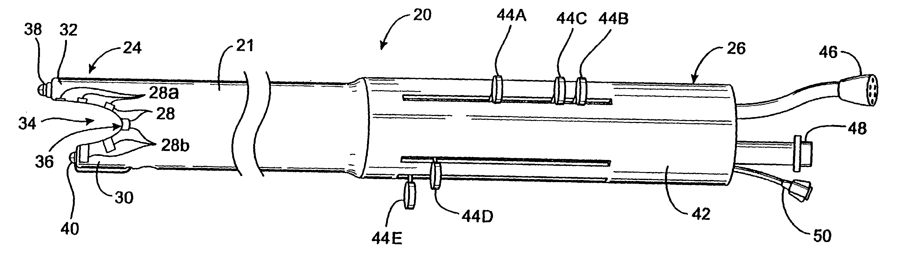
[0012] In addition, a mechanism may be provided for urging all or part of the working end against the epicardium to ensure adequate contact with the ablation devices. This mechanism may be, for example, one or more suction holes in the working end through which suction may be applied to draw the working end against the epicardium, or an inflatable balloon mounted to the outer side of the working end such that, upon inflation, the balloon engages the inner wall of the pericardium and forces the working end against the epicardium. This also functions to protect extracardiac tissues such as the pericardium from injury by retracting such tissues away from the epicardial region which is being ablated, and, in the case of the balloon, providing an insulated barrier between the electrodes of the ablation probe and the extracardiac tissues.
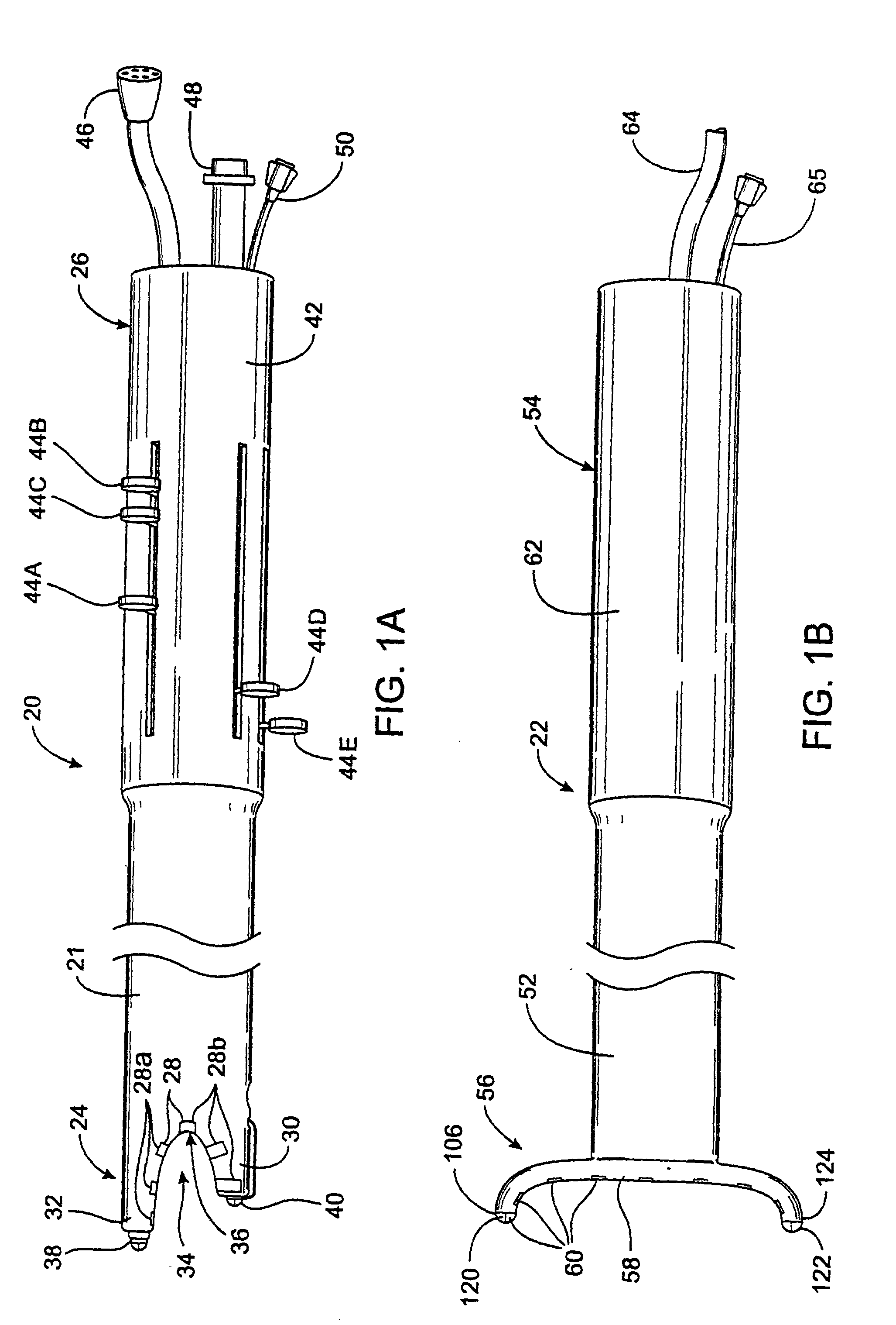
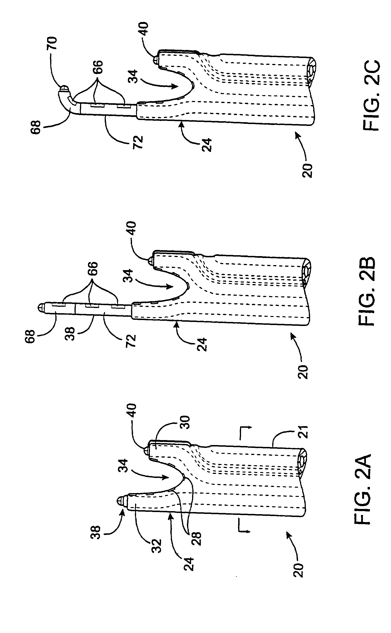
[0013] The apparatus may be either a single integrated device or two or more devices which work in tandem. In either case, the apparatus may have two or more tips at the working end which are positioned on opposing sides of a tissue layer such as a pericardial reflection. A device may be provided for approximating the two free ends on opposing sides of the tissue layer, such as an electromagnet mounted to one or both of the free ends. In this way, a continuous lesion may be created in the myocardium from one side of the pericardial reflection to the other without puncturing or cutting away the pericardial reflection.
[0023] The device also has a fluid inlet and a fluid outlet for delivering and withdrawing fluid from within the closed wall formed by the inner lip. The fluid is preferably a conductive fluid, such as hypertonic saline, which conducts energy from the ablating element, such as an RF electrode, to the tissue. The fluid is preferably delivered along a short axis of the ablating element so that the temperature change across the ablating element is minimized.
[0026] In a further aspect of the invention, the ablating element preferably produces focused ultrasound in at least one dimension. An advantage of using focused ultrasound is that the energy can be concentrated within the tissue. Another advantage of using focused ultrasound is that the energy diverges after reaching the focus thereby reducing the possibility of damaging tissue beyond the target tissue as compared to collimated ultrasonic energy. When ablating epicardial tissue with collimated ultrasound, the collimated ultrasound energy not absorbed by the target tissue travels through blood and remains concentrated on a relatively small area when it reaches another surface such as the endocardial surface on the other side of a heart chamber. The present invention reduces the likelihood of damage to other structures since the ultrasonic energy diverges beyond the focus and is spread over a larger area. The focused ultrasound has a focal length of about 2 to 20 mm, more preferably about 2 to 12 mm and most preferably about 8 mm in at least one dimension. The focused ultrasound also forms an angle of 10 to 170 degrees, more preferably 30 to 90 degrees and most preferably about 60 degrees as defined relative to a focal axis. The focused ultrasound preferably emits over 90%, and more preferably over 99%, of the energy within the angles and focal lengths described above. The focused ultrasound may be produced in any manner and is preferably produced by a curved transducer with a curved layer attached thereto. The ultrasound is preferably not focused, and may even diverge, when viewed along an axis transverse to the focal axis.
[0032] The device may be adhered to tissue with suction although suction is not required. The device may also have a membrane filled with a substance which transmits the ultrasound energy to the tissue. The membrane conforms to the tissue and eliminates air gaps between the device and tissue to be ablated. Alternatively, the device may have a solid element which contacts the tissue and transmits the ultrasound energy to the tissue. The device may also be used with a gel applied to the tissue which transmits the ultrasound energy and eliminates air gaps.

Problems solved by technology

This location creates significant difficulties for endocardial ablation devices for several reasons.
Second, the elongated and flexible endovascular ablation devices are difficult to manipulate into the complex geometries required for forming the pulmonary venous lesions and to maintain in such positions against the wall of the beating heart.
This is very time-consuming and can result in lesions which do not completely encircle the pulmonary veins or which contain gaps and discontinuities.
Third, visualization of endocardial anatomy and endovascular devices is often inadequate and knowing the precise position of such devices in the heart can be difficult, resulting in misplaced lesions.
However, on the left side of the heart where the pulmonary venous lesions are formed, thrombus can be carried by the bloodstream into the coronary arteries or the vessels of the head and neck, potentially resulting in myocardial infarction, stroke or other neurologic sequelae.
Finally, the heat generated by endocardial devices which flows outward through the myocardium cannot be precisely controlled and can damage extracardiac tissues such as the pericardium, the phrenic nerve and other structures.

Method used


Image

  • Device and method for forming a lesion
  • Device and method for forming a lesion
  • Device and method for forming a lesion

Examples


Embodiment Construction

[0114] FIGS. 1A-1B illustrate a first embodiment of the apparatus of the invention. In this embodiment, the apparatus comprises a left ablation probe 20, shown in FIG. 1A, and a right ablation probe 22, shown in FIG. 1B, which work in tandem to form a transmural lesion isolating the pulmonary veins from the surrounding myocardium. Left ablation probe 20 has a flexible shaft 21 extending to a working end 24 configured for insertion into the chest cavity through a small incision, puncture or access port. Opposite working end 24, shaft 21 is attached to a control end 26 used for manipulating the working end 24 from outside the chest. Shaft 21 is dimensioned to allow introduction through a small incision in the chest, preferably in a subxiphoid location, and advanced to the pulmonary veins on the posterior side of the heart. Preferably, shaft 21 is configured to be flexible about a first transverse axis to allow anterior-posterior bending and torsional flexibility, but relatively stiff ...


PUM


Abstract

A control system alters one or more characteristics of an ablating element to ablate tissue. In one aspect, the control system delivers energy nearer to the surface of the tissue by changing the frequency or power. In another aspect, the ablating element delivers focused ultrasound which is focused in at least one dimension. The ablating device may also have a number of ablating elements with different characteristics such as focal length.

Description

CROSS-REFERENCES TO RELATED APPLICATIONS[0001] This application is a continuation-in-part of application Ser. No. 09 / 507,336 filed Feb. 18, 2000 which is a continuation-in-part of application Ser. No. 09 / 356,476, filed Jul. 19, 1999, which is a continuation-in-part of application Ser. No. 09 / 157,824, filed Sep. 21, 1998, which is a continuation-in-part of application Ser. No. 08 / 943,683, filed Oct. 15, 1997, which is a continuation-in-part of application Ser. No. 08 / 735,036, filed Oct. 22, 1996, the complete disclosures of which are hereby incorporated herein by reference for all purposes.FIELD OF THE INVENTION[0002] This invention relates generally to devices and methods for ablating tissue. The diagnosis and treatment of electrophysiological diseases of the heart, and more specifically to devices and methods for epicardial mapping and ablation for the treatment of atrial fibrillation, are described in connection with the devices and methods of the present invention.BACKGROUND OF T...

Claims


Application Information

Patent Timeline
Patent Type & Authority Applications(United States)
IPC IPC(8): A61B5/042A61B8/00A61B17/00A61B17/22A61B17/34A61B18/00A61B18/02A61B18/04A61B18/14A61B18/18A61B19/00A61N1/06A61N1/362A61N7/00A61N7/02
CPCA61B5/0422A61B17/22012A61B17/2202A61B18/00A61B18/02A61B18/1402A61B18/148A61B18/1482A61B18/1492A61B2017/00039A61B2017/00243A61B2017/00247A61B2017/00252A61B2017/003A61B2017/22077A61B2017/3419A61B2018/00023A61B2018/0016A61B2018/00232A61B2018/00261A61B2018/00285A61B2018/00291A61B2018/00351A61B2018/00363A61B2018/00392A61B2018/00577A61B2018/00654A61B2018/00797A61B2018/00839A61B2018/142A61B2018/1467A61B2018/1472A61B2218/002A61B2218/007A61N1/06A61N1/362A61N7/02A61N2007/0065A61N2007/0078A61N2007/027A61B2090/3782A61B2090/3614A61B2090/395A61B34/20A61N1/3629A61B5/287
Inventor PLESS, BENJAMINANDERSON, SCOTT C.PODMORE, JONATHAN L.VASKA, MATTHIASCROWE, JOHN E.RICHMAN, ROXANNE L.CICIARELLI, TIMOTHYGALLUP, DAVID A.ULSTAD, JACK E. JR.
Owner EPICOR
Why Eureka
Try Eureka