Simultaneous ammonia and fluoride treatment for wastewater

Inactive Publication Date: 2002-10-17
UBS AG STAMFORD BRANCH AS COLLATERAL AGENT
View PDF0 Cites 24 Cited by
  • Summary
  • Abstract
  • Description
  • Claims
  • Application Information

AI Technical Summary

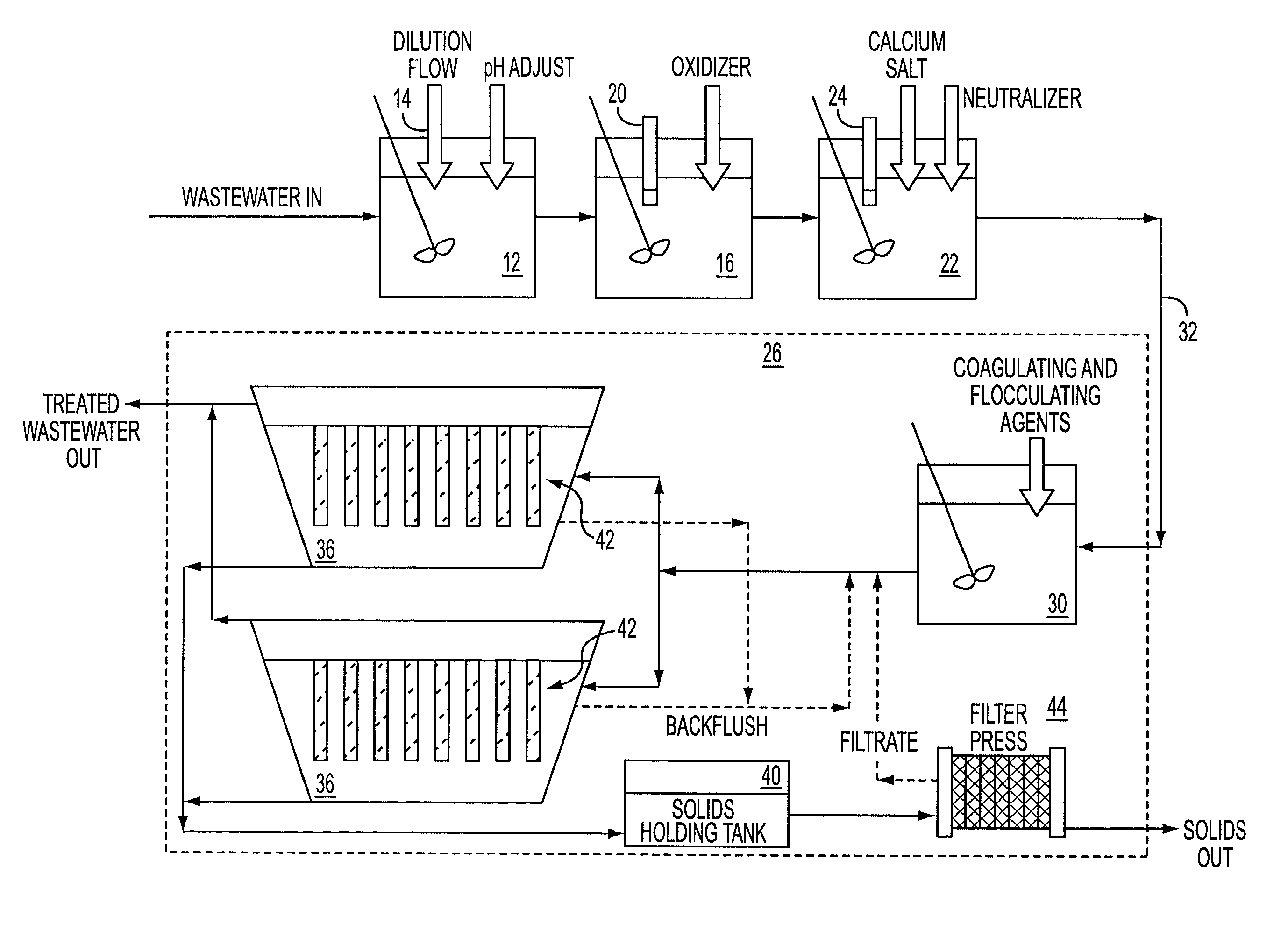
Benefits of technology

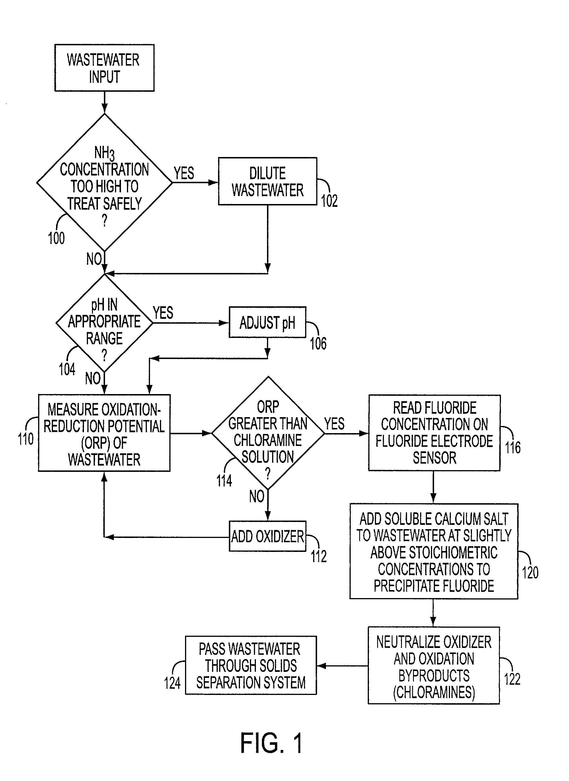
0009] Accordingly, it is an object of the present invention to provide an improved system and method for removing ammonia and fluoride from wastewater. In particular, the inventor has found that a significant improvement in the prior art process for removal of fluoride from wastewater can be achieved by treating the wastewater with an oxidizer to chemically destroy ammonia before adding calcium salts to precipitate calcium fluoride. It is another object of the current invention to reduce the costs of removing fluoride from wastewater by reducing the chemical requirements and generating a low volume waste stream that can be more easily disposed of.
0010] In general, the current invention present a process by which ammonia is chemically destroyed prior to treatment of fluoride. The wastewater is then treated with near stoichiometric amounts of calcium salts to precipitate calcium fluoride. Finally, suspended solids are removed from the wastewater. The final step can be a conventional settling tank or some sort of filtration system. A preferred solids removal process is a single pass, low pressure, high flow rate filtration step, such as the EnChem system available from MicroBar. Options include neutralization of excess oxidizer and byproducts, and removal of byproducts with activated carbon. The neutralization of excess oxidizer and byproducts can be done chemically prior to filtration. Often it is more convenient to do this step after filtration, when the solids-free water can be treated with reducing agents and/or contacted with activated carbon.

Problems solved by technology

Additionally, ammonia interferes with the precipitation of calcium fluoride, necessitating the use of large excess amounts of calcium salts in the treatment process.
This is very energy intensive, requires the addition of large amounts of caustic, and should be done without solids in the wastewater.
However, RO is sensitive to membrane fouling by scale formation or biological growth on the filter membrane.
However, the elevated ammonia concentrations in the concentrate hinders calcium fluoride precipitation necessitating use of large excesses of calcium salts.
However, this process is not efficient for wastewater with high ammonia concentrations because the resins must be regenerated often at high chemical costs.
Other cations such as calcium, magnesium, sodium, and the like will interfere

Method used


Image

  • Simultaneous ammonia and fluoride treatment for wastewater
  • Simultaneous ammonia and fluoride treatment for wastewater
  • Simultaneous ammonia and fluoride treatment for wastewater

Examples


Embodiment Construction

[0034] The following experiments are offered for illustrative purposes only, and are not intended to limit the scope of the present invention in any way. The present invention is carried out using a wastewater stream having a total stream of dilute fluoride rinses and buffered oxide etch (BOE) solutions that amount to about 2000 m.sup.3 / month.

[0035] In particular, the BOE solution itself amounts to about 75 m.sup.3 / month, with a ramp up to about 150 m.sup.3 / month. Even though the volume is small, the total amount of fluoride and ammonia is large. The BOE waste stream accounts for about 50% of the total fluoride waste from the plant.

[0036] In one example, the ammonium fluoride concentration is in the range of 3-8%. There is 0.2-0.6% (all wt %) triammonium phosphate. The silica concentration is in the low few hundred ppm. No substantial amount of organic matter was present. A 20 m.sup.3 sample was collected and found to have 5.2% fluoride by weight. Incoming pH was also tested and fou...


PUM

PropertyMeasurementUnit
Concentrationaaaaaaaaaa
Solubility (mass)aaaaaaaaaa
Reduction potentialaaaaaaaaaa

Abstract

An improved method of treating wastewater to remove ammonia and fluoride is provided. The method comprises the steps of chemical destruction of ammonia with an oxidizing agent, followed by treatment with calcium salts to precipitate insoluble calcium fluoride, and filtration to remove the precipitate.

Description

[0001] This application claims priority to U.S. Provisional Patent Application, Serial No. 60 / 235,992 filed Sep. 26, 2000, the entire disclosure of which is hereby incorporated by reference.[0002] The present invention relates generally to a treatment for wastewater. More specifically, the present invention provides an enhanced system and more efficient process of treating industrial wastewater to remove ammonia and fluoride sequentially by a process of chemical destruction of ammonia, treatment with near stoichiometric amounts of calcium salts, and filtration.[0003] Buffered oxide etch processes are used in the semiconductor industry to process silica wafers. The buffered oxide etch process requires the use of high concentrations of ammonia fluoride or ammonium bifluoride which end up in the semiconductor wastewater. Fluoride must be removed from wastewater streams prior to discharge into the city water systems, and local discharge limits can be lower than 5 ppm. Discharge limits f...

Claims


Application Information

Patent Timeline
IPC IPC(8): C02F1/00C02F1/28C02F1/44C02F1/52C02F1/66C02F1/72C02F1/76C02F1/78C02F9/00
CPCC02F1/001Y10S210/915C02F1/44C02F1/5245C02F1/66C02F1/72C02F1/722C02F1/76C02F1/78C02F9/00C02F2101/14C02F2101/16C02F2209/001C02F2209/003C02F2209/01C02F2209/04C02F2209/06C02F1/283
Inventor KRULIK, GERALD A.
Owner UBS AG STAMFORD BRANCH AS COLLATERAL AGENT
Why Eureka
Try Eureka