Method and arrangement for producing electrical energy at a pulp mill

a pulp mill and electrical energy technology, applied in the field of methods, can solve the problems of low electricity yield and condensation solution efficiency, low efficiency of recovery boilers, and high temperature corrosion and clogging risks, and achieve the effects of preventing the preheating of combustion air with flue gases, reducing the risk of high-temperature corrosion and clogging, and increasing the efficiency of electricity production

Inactive Publication Date: 2002-12-26
ANDRIZ OY
View PDF0 Cites 17 Cited by
  • Summary
  • Abstract
  • Description
  • Claims
  • Application Information

AI Technical Summary

Benefits of technology

0019] One advantage of the invention is to effect in a recovery boiler combusting waste liquid in a pulp mill an implementation in which the feed water may be heated to a relatively high temperature by means of bled steam flows of the turbine and thus increase the efficiency of electricity production (or, more exactly, the amount of electricity produced in relation to the amount of process steams, i.e., the overall electrical efficiency in back pressure production). The low-level temperature of the flue gases is then recovered into combustion air or boiler feed water. In recovery boilers, the preheating of combustion air with flue gases has been prevented by the fouling properties of the flue gases clogging conventional flue gas / air preheaters. In this invention, this problem is avoided by using a hot electrostatic precipitator, with the help of which also reduction of nitrogen oxides in the flue gases of the recovery boiler may be effected, which nowadays is also current, as so far there is no SCR catalyst available operating reliably, if the flue gases of the recovery boiler have not been cleaned of fly ash. A known solution for the operation of a SCR-catalyst, when the flue gases are fouling, is to locate a purifying apparatus for nitrogen oxides operating on an SCR-basis after a cold (120-200.degree. C.) electrostatic precipitator so that the temperature is raised to the operating temperature of the catalyst, which is in this case about 260-330.degree. C., by means of a regenerator and additional combustion. A disadvantage of this solution is thermal loss, which has to be compensated by fuel combustion. The lost temperature difference in the flue gases is typically 20-50.degree. C. And further, the apparatus is expensive.

Problems solved by technology

The ratio of heat and electricity obtained by means of the recovery boiler is disadvantageous in present-day sulfate pulp mills.
The heat production need may be covered by the recovery boiler better than before, due to decreased heat consumption by the processes, but the electricity yield as well as the efficiency of condensation solutions is low.
Because the flue gas particles of the recovery boiler containing alkalis, sulfur and chlorine are easily fusible and tend to fasten onto the heat transfer surfaces, the recovery boiler has a risk of high-temperature corrosion and clogging.
Higher final temperatures of flue gases would lead to a lower efficiency due to greater flue gas losses, as, due to impurities contained in the flue gas, the recovery boilers have not been provided with flue gas-heated preheaters of air to decrease the final temperature of the flue gas.
Back pressure production makes the low pressure preheating typically inappropriate and high-pressure preheating raises the temperature of the feed water so that it would lead to increased temperatures of discharging flue gases, which in turn would decrease said efficiency, unless it would be possible to cool the flue gases after the economizer in an economical way.
Earlier, economical use of the SCR-method was not possible due to the low temperature of the flue gas, which had been discharged from the recovery boiler and cleaned of particulate matter.
A disadvantage of this solution is thermal loss, which has to be compensated by fuel combustion.
And further, the apparatus is expensive.

Method used


Image

  • Method and arrangement for producing electrical energy at a pulp mill
  • Method and arrangement for producing electrical energy at a pulp mill
  • Method and arrangement for producing electrical energy at a pulp mill

Examples


Embodiment Construction

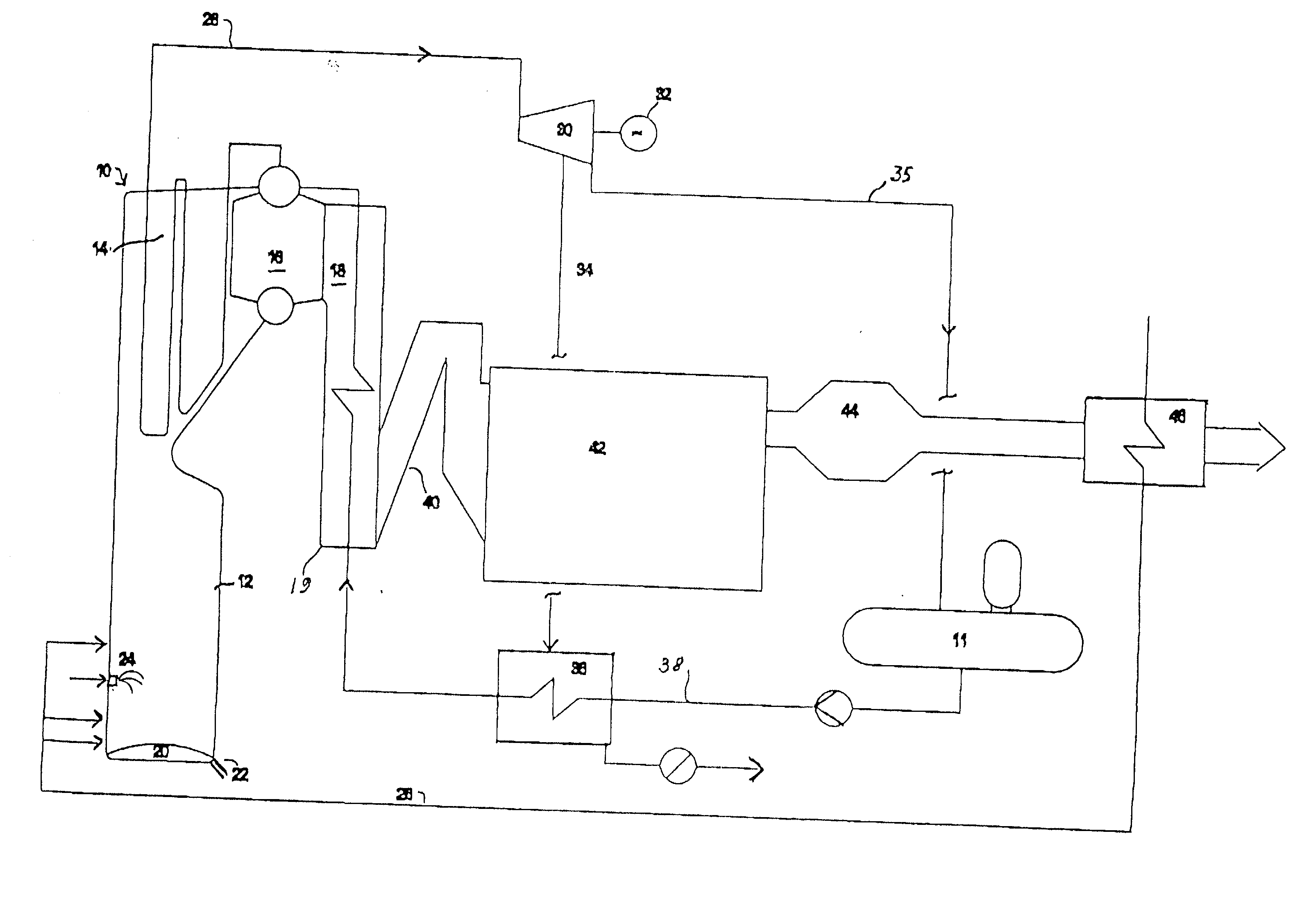
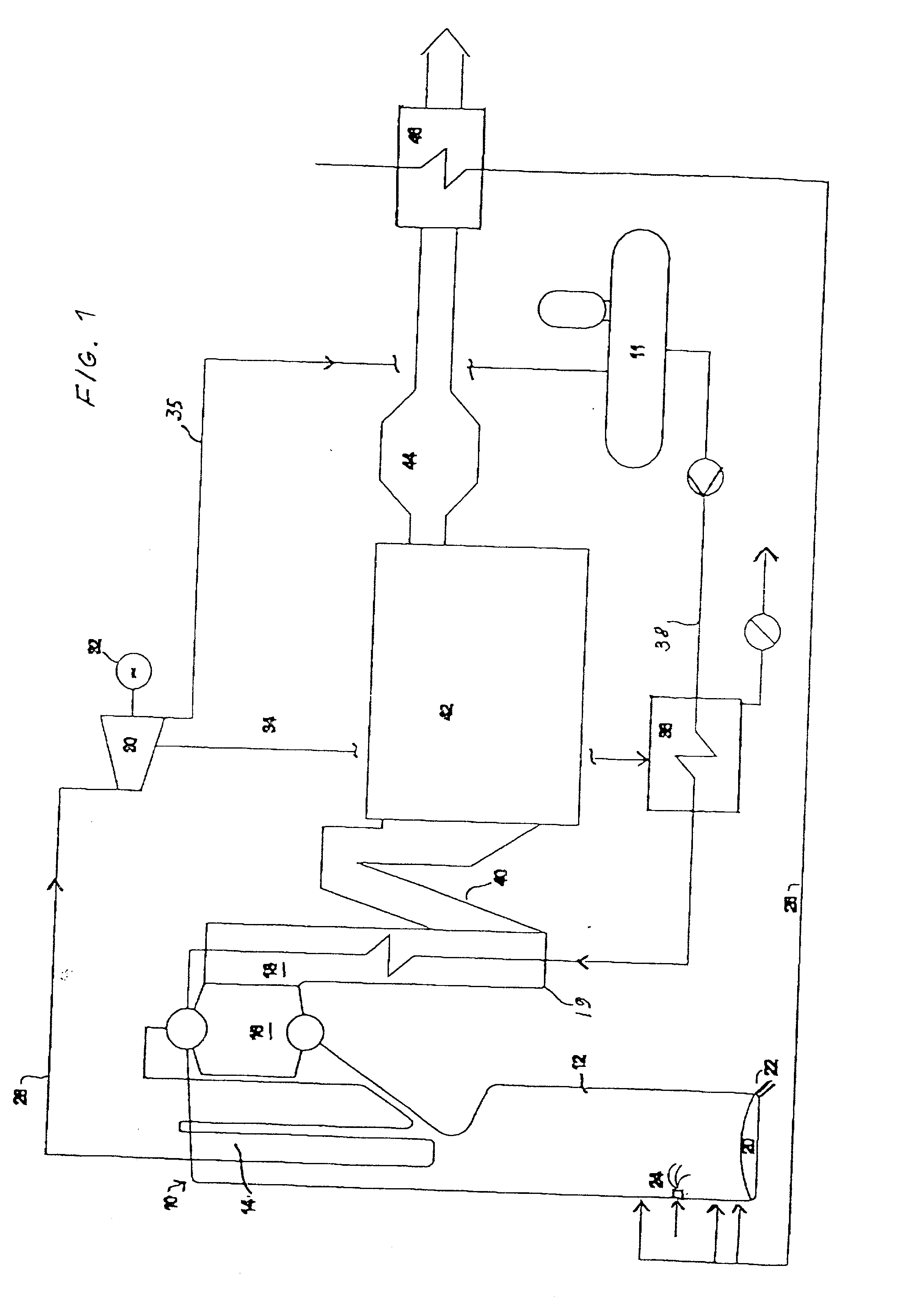
[0023] FIG. 1 illustrates a recovery boiler 10 known per se which comprises a furnace 12 and heat recovery surfaces: a superheater 14, a steam-generating bank 16 and an economizer 18. The economizer can comprise one or more economizers. Black liquor is introduced into the boiler via nozzles 24. Prior to the boiler, the black liquor has been concentrated in the evaporation plant to a dry solids content of more than 80 weight percent, typically about 80-95 weight percent of dry solids, preferably about 85-90 weight percent. A preferred method of reaching such a high dry solids content in black liquor evaporation is the method described in FI patent application 974345.

[0024] Preheated combustion air is also introduced into the furnace via line 26. The excess air ratio in the combustion is low, less than 2 volume percent, preferably 1-1.5 volume percent. During the combustion, chemicals contained in the black liquor form a char bed 20 at the bottom of the furnace, wherefrom the chemical...


PUM

PropertyMeasurementUnit
temperatureaaaaaaaaaa
pressureaaaaaaaaaa
temperatureaaaaaaaaaa

Abstract

The invention relates to a method and an arrangement in the production of electric energy in a boiler plant of a pulp mill. Black liquor having a dry solids content of more than 80% and combustion air are fed into a furnace of a recovery boiler for combusting black liquor and recovering chemicals contained therein. The flue gases generated in the combustion are led into an economizer of the recovery boiler, in which economizer the feed water for the boiler is heated, and after the economizer to gas cleaning. The feed water is led from the economizer onto the steam-generating bank at a temperature below the saturation temperature and further into a superheater to produce steam having a pressure of more than 80 bar. The steam is led from the recovery boiler to a steam turbine to produce electricity. The temperature of the feed water being led into the economizer is regulated by means of bleed steam of the turbine so that the flue gases exit the economizer at a temperature of more than 250° C. and that after the economizer the flue gases are cleaned in at least a hot electrostatic precipitator and the cleaned flue gases are cooled by the combustion air or the feed water.

Description

[0001] Priority is claimed to U.S. Provisional Patent Application Serial No. 60 / 293,526, filed on May 29, 2001, and which is incorporated by reference herein.BACKGROUND AND SUMMARY OF INVENTION[0002] The present invention relates to a method of producing additional electrical energy in a boiler plant of a pulp mill. Black liquor preferably having a dry solids content of over 80% and combustion air is fed into the furnace of a chemical recovery boiler for burning black liquor and recovering chemicals therefrom. The flue gases generated in the combustion are led to an economizer of the recovery boiler, in which economizer feed water for the boiler is heated, and after the economizer to a device that cleans the flue.[0003] Feed water flows from the economizer to the steam-generating bank of the boiler, and into the superheater for producing steam preferably having a pressure of more than 80 bar. The steam flows from the recovery boiler to a steam turbine for producing electricity. Stea...

Claims


Application Information

Patent Timeline
Patent Type & Authority Applications(United States)
IPC IPC(8): D21C11/12F01K3/24F01K7/34F01K7/16F22B1/20F22D1/32F23G7/04F23J15/00
CPCD21C11/12Y02E20/12F01K3/247
Inventor SAVIHARJU, KARISIMONEN, JORMA
Owner ANDRIZ OY
Why Eureka
Try Eureka