Optically variable marking

a technology markings, applied in the field of optically variable markings, can solve the problems of the clc layer's reflection colour shifting to shorter wavelengths, devices described in prior art,

Inactive Publication Date: 2003-01-16
MERCK PATENT GMBH
View PDF6 Cites 32 Cited by
  • Summary
  • Abstract
  • Description
  • Claims
  • Application Information

AI Technical Summary

Benefits of technology

[0008] The optically variable marking according to the present invention overcomes the limitations of EP 0 435 029 by having both reflective and transmissive views possible. An advantage over the security markings described in U.S. Pat. No. 5,678,863 is that the document itself needs no pre-treatment but can include the marking as part of its structure. For example, the described marking can be added to the document for example by weaving it into the paper using a process known to one skilled in the art or by applying it as a transfer using a hot stamping foil process. In addition, in the present invention no visible markings are seen when the device is viewed in reflection, giving the document a hidden feature. Furthermore, the optically variable marking of the present invention is easy to manufacture, as will be shown below.
[0009] Another advantage of the optically variable marking of the present invention compared to prior art devices is that the optically variable film can be made ready for use in one roll to roll process involving coating, laminating, curing and rewinding. At this stage the product is a reflecting film. Later treatment of the film by exposure to laser energy can remove the metallised layer in defined regions. The design can therefore be changed without the necessity of changing the material of the document itself.
[0044] By varying the concentration of the multifunctional mesogenic or non mesogenic compounds the crosslink density of the polymer film and thereby its physical and chemical properties such as the glass transition temperature, which is also important for the temperature dependence of the optical properties of the polymerised film, the thermal and mechanical stability or the solvent resistance can be tuned easily.
[0054] Polymerisation of the CLC material takes place by exposing it to heat or actinic radiation. Actinic radiation means irradiation with light, like UV light, IR light or visible light, irradiation with X-rays or gamma rays or irradiation with high energy particles, such as ions or electrons. Preferably polymerisation is carried out by UV irradiation at a non-absorbing wavelength. As a source for actinic radiation for example a single UV lamp or a set of UV lamps can be used. When using a high lamp power the curing time can be reduced. Another possible source for actinic radiation is a laser, like e.g. a UV laser, an IR laser or a visible laser.
[0062] Other additives, like, e.g., chain transfer agents, can also be added to the polymerisable LC material in order to modify the physical properties of the resulting polymer film. When adding a chain transfer agent, such as monofunctional thiol compounds like, e.g., dodecane thiol or multifunctional thiol compounds like, e.g., trimethylpropane tri(3-mercaptopropionate), to the polymerisable material, the length of the free polymer chains and / or the length of the polymer chains between two crosslinks in the inventive polymer film can be controlled. When the amount of the chain transfer agent is increased, the polymer chain length in the obtained polymer film is decreasing.
[0068] This marked foil can then be split into thin threads which can be woven into a security paper in accordance with procedures known to one skilled in the art. When viewed under normal conditions in reflected light, only the effect of the optically variable layer is seen. However, when held against strong back lighting the marked areas will become visible. This gives an additional effect similar to a watermark which will be difficult to copy.

Problems solved by technology

However, the devices described in prior art have several drawbacks.
This results in a shift of the reflection colour of the CLC layer to shorter wavelengths when being viewed at increasing angles from normal.

Method used


Image

  • Optically variable marking
  • Optically variable marking

Examples


Embodiment Construction

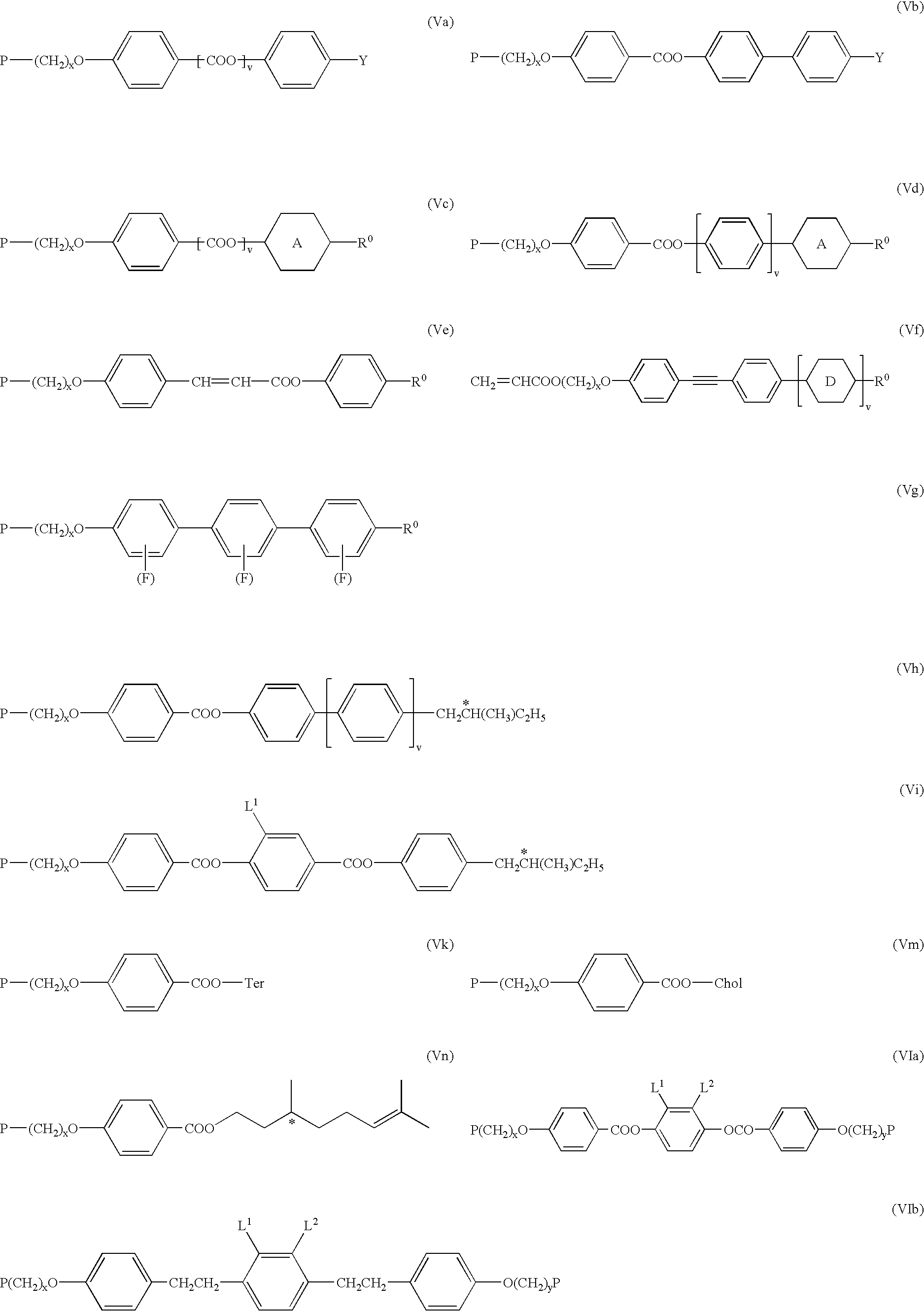
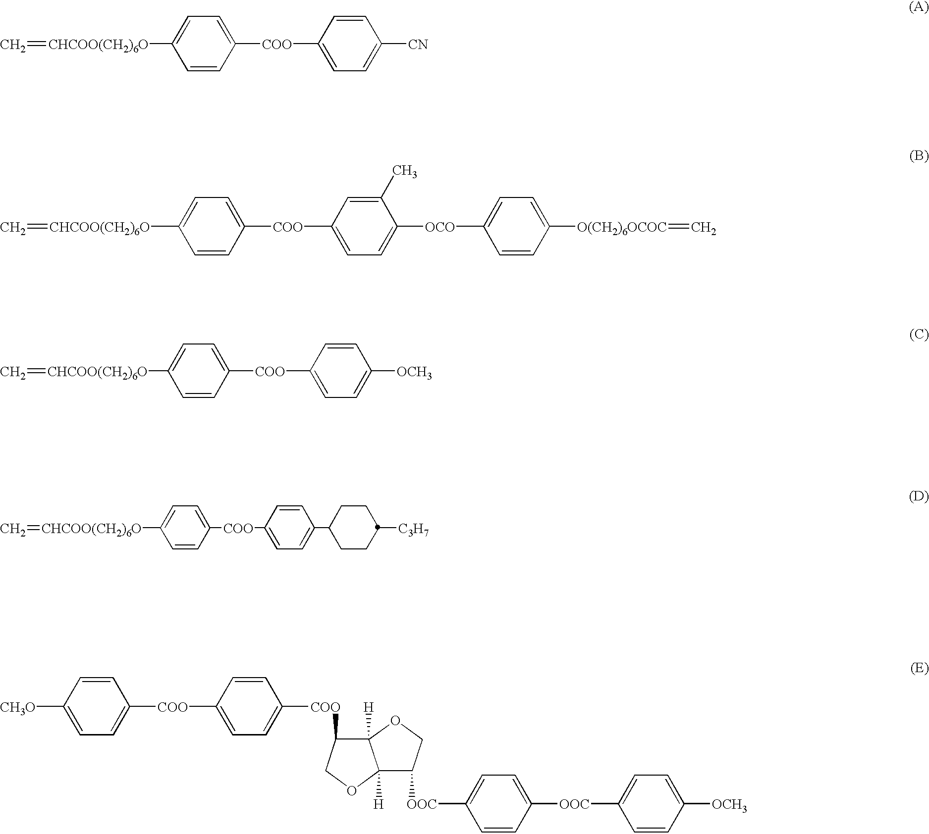
[0073] The following polymerisable CLC mixture is prepared

[0074] compound (A) 32.60%

[0075] compound (B) 3.00%

[0076] compound (C) 30.16%

[0077] compound (D) 29.56%

[0078] compound (E) 3.59%

[0079] Irgacure 651 1.08% 2

[0080] The polymerisable mesogenic compounds (A), (B) and (C) can be prepared according to or in analogy to the methods described in D. J. Broer et al., Makromol.Chem. 190, 3201-3215 (1989). The polymerisable mesogenic compound (D) and its preparation are described in GB 2,280,445. The chiral dopant (E) and its preparation are described in WO 98 / 00428. Irgacure 651 is a commercially available photoinitiator (Ciba Geigy).

[0081] The mixture is coated onto the PET side of a metallised PET film and polymerised by irradiation with UV light. Preferably the PET is darkened to about 95% absorbance. The coated structure is then exposed to laser light (Nd-YAG laser,1064 nm, 100 W) through the coating, and the aluminium coating is removed from the film only in the places exposed to la...


PUM

PropertyMeasurementUnit
thicknessaaaaaaaaaa
thicknessaaaaaaaaaa
thicknessaaaaaaaaaa

Abstract

The invention relates to an optically variable marking comprising a semiopaque substrate with a first surface that is covered with an optically variable layer that is for example a liquid crystal polymer layer or a layer comprising pearlescent pigments, and a second surface that is partially covered with a metal layer in the shape of a pattern, to methods of its preparation and to its use for decorative or security applications.

Description

[0001] The invention relates to an optically variable marking comprising an optically variable layer that is for example a liquid crystal polymer layer or a layer comprising pearlescent pigments, to methods of preparing such an optically variable marking, and to its use for decorative or security applications.BACKGROUND AND PRIOR ART[0002] The use of liquid crystal polymers films as security devices has been reported in prior art. EP 0 435 029 discloses a data carrier with an optically variable security element that contains an oriented liquid crystal polymer. U.S. Pat. No. 5,678,863 (corresponding to GB 2,268,906) discloses a security marking for a document of value comprising a watermark coated with a cholesteric liquid crystal material producing optical effects which differ when viewed in transmitted and reflected light. The cholesteric liquid crystal material is for example a liquid crystal polymer.[0003] However, the devices described in prior art have several drawbacks. Thus, ...

Claims


Application Information

Patent Timeline
Patent Type & Authority Applications(United States)
IPC IPC(8): B42D15/10B42D25/00G02B5/30G03H1/18G09F19/12
CPCB42D2033/26B42D25/00Y10T428/1036Y10T428/12438Y10T428/24736Y10T428/24322Y10T428/1086Y10T428/24917C09K2323/06C09K2323/03B42D25/328B42D25/373B42D25/364
Inventor KUNTZ, MATTHIASDELP, REINERRIDDLE, RODNEYPATRICK, JOHNHAMMOND-SMITH, ROBERT
Owner MERCK PATENT GMBH
Why Eureka
Try Eureka