Apparatus and method for large area chemical vapor deposition using multiple expanding thermal plasma generators

a technology of thermal plasma generator and large area, applied in the direction of chemical vapor deposition coating, coating, plasma technique, etc., can solve the problems of inability to efficiently produce a coating, system is incapable of coating a single surface of, for example, a planar substrate, and its operating parameters, such as arc-to-arc spacing, arc-to-substrat distance, and deposition pressure, are not adapted to etp deposition, etc., to achieve efficien

Inactive Publication Date: 2003-04-17
SABIC INNOVATIVE PLASTICS IP BV
View PDF6 Cites 49 Cited by
  • Summary
  • Abstract
  • Description
  • Claims
  • Application Information

AI Technical Summary

Benefits of technology

[0007] The present invention provides an ETP coating apparatus and process particularly adapted to efficiently coat large substrates. The invention can be configured so as to provide coatings having desirable properties, including uniformity and reproducibility.
[0043] Spacing of the ETP generating means also has an effect on the uniformity of the coating deposited on the substrate. In order to maximize uniformity, it is preferred to provide a spacing such that there is overlap between the edge portions of the plurality of plasma plumes. The precise amount of overlap will depend on numerous factors, such as the size of the plasma produced by the ETP generating means, the distance of the ETP generating means from the substrate, power to the ETP generating means, and flow rates of various reagents. It is a relatively simple matter to determine by simple experimentation the optimum spacings for each coating apparatus. It is often found, for example, that excellent results are obtained when the anode (as shown in FIG. 4) of each ETP generating means is about 20-40 cm and especially about 25-28 cm from the substrate at a chamber pressure of about 30 to about 60 millitorr. The spacing (D in FIG. 1) between center axes of the ETP generating means is generally about 10-21 cm and especially about 12-18 cm for wall-stabilized DC arc plasma generators operated at a pressure of about 200-800 torr.
[0048] It is also contemplated to provide for motion of the plasma plumes impinging on the substrate, so as to scan a region of the substrate, This may be achieved by mounting the ETP generating means or the nozzles associated therewith on swivels that may be manually or computer controlled. It may also be achieved by mounting one or more magnets on or near the walls of the deposition chamber, thereby permitting magnetic variation of the direction and shape of the plasma plume.

Problems solved by technology

A problem with ETP deposition as described in the prior art is its incapability of efficiently producing a coating over a large area of a substrate.
Such a system is incapable being used to coat a single surface of, for example, a planar substrate.
As such, their operating parameters, such as arc-to-arc spacing, arc to substrate distance, and deposition pressure, are not adapted to ETP deposition.

Method used


Image

  • Apparatus and method for large area chemical vapor deposition using multiple expanding thermal plasma generators
  • Apparatus and method for large area chemical vapor deposition using multiple expanding thermal plasma generators
  • Apparatus and method for large area chemical vapor deposition using multiple expanding thermal plasma generators

Examples


example 2

[0058] The procedure of Example 1 was repeated, except that a curved substrate, adapted for use as an automobile window, was employed. The increase in Taber haze was measured at the centers of each side of five 10.times.10-cm sections of the substrate. The average increase was 2.7% with a standard deviation of 0.4%. Thus, the method of the invention was shown to be effective on curved as well as flat substrates.

example 3

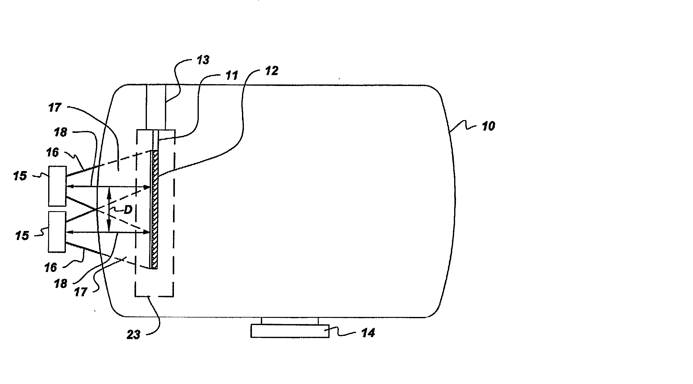
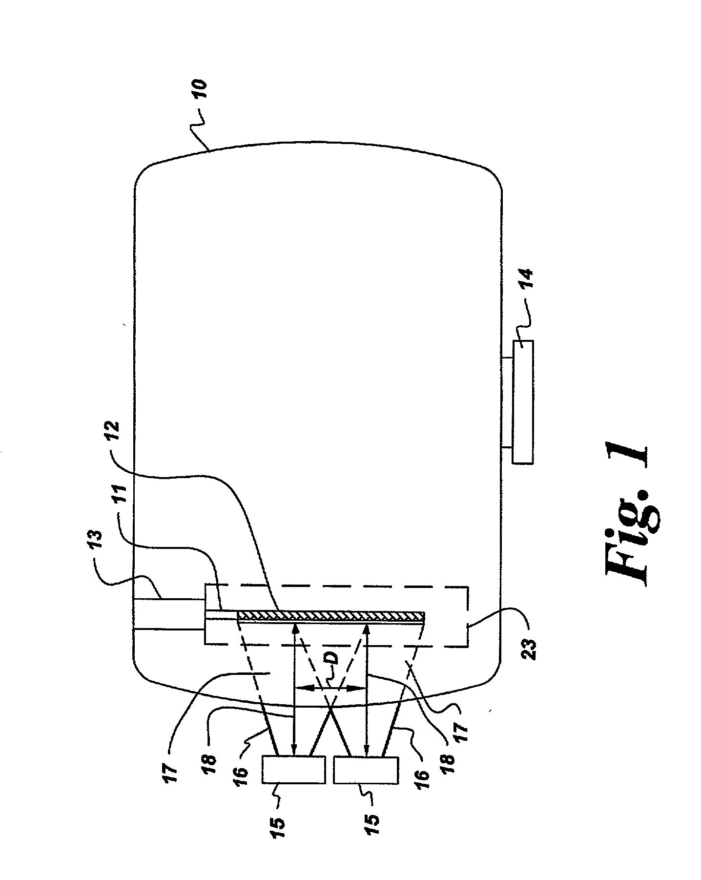
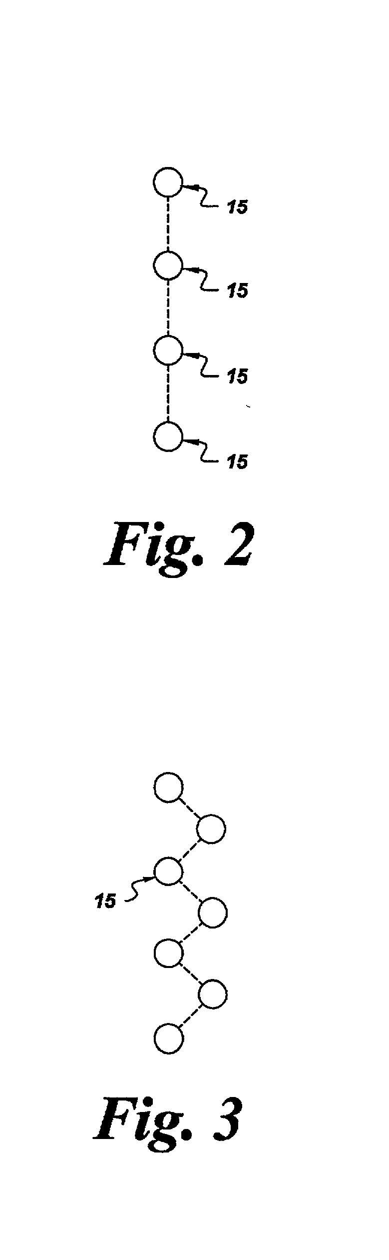
[0059] The procedure of Example 1 was repeated, except that an array of three ETP generating means, arranged in a zigzag configuration, was employed. The ETP generating means were arranged so that the vertical distance between the centers of the plasma plumes was 15 cm and the horizontal distance was about 26 cm. A retractable shutter having an aperture 20 cm wide was placed between the ETP generating means and the substrate.

[0060] Coating thicknesses and Taber haze increases were measured as in Example 1 Thicknesses were 4.1 micron in average with a standard deviation of 0.4 micron. The average Taber haze increase was 1.9% with a standard deviation of 0.3%.

example 4

[0061] The procedure of Example 3 was repeated, with the exception that a curved substrate, adapted for use as an automobile window, was employed. The average Taber haze increase was 2.3% with a standard deviation of 0.5%.


PUM

PropertyMeasurementUnit
angleaaaaaaaaaa
distanceaaaaaaaaaa
distanceaaaaaaaaaa

Abstract

Chemical vapor deposition is performed using a plurality of expanding thermal plasma generating means to produce a coating on a substrate, such as a thermoplastic and especially a polycarbonate substrate. The substrate is preferably moved past the generating means. Included are methods which coat both sides of the substrate or which employ multiple sets of generating means, either in a single deposition chamber or in a plurality of chambers for deposition of successive coatings. The substrate surfaces spaced from the axes of the generating means are preferably heated to promote coating uniformity.

Description

BACKGROUND OF INVENTION[0001] This invention relates to plasma enhanced chemical vapor deposition. More particularly, it relates to deposition in an expanding thermal plasma (hereinafter referred to as "ETP") system to coat large areas of a substrate.[0002] The use of ETP to deposit coatings, especially protective coatings, on substrates is known. For example, U.S. Pat No. 6,110,544 describes a method of forming coatings on a plastic substrate such as polycarbonate. The coatings that may be deposited include silicon oxide-based hardcoats, which can protect the plastic surface from abrasion. Also capable of deposition are metal oxide-based coatings such as zinc oxide. Coatings of these types are produced by introducing an organosilicon or organometallic compound into an ETP and causing the plasma stream produced by said ETP to impinge upon the surface of the substrate. By using ETP, particularly those using equilibrium thermal plasma arc generators, high coating deposition rates may ...

Claims


Application Information

Patent Timeline
Patent Type & Authority Applications(United States)
IPC IPC(8): C23C16/40C23C16/513H01J37/32H05H1/44
CPCC23C16/401H05H1/44H01J37/32009C23C16/513
Inventor YANG, BARRY LEE-MEANIACOVANGELO, CHARLES DOMINICBROWALL, KENNETH WALTERGASWORTH, STEVEN MARCMORRISON, WILLIAM ARTHURJOHNSON, JAMES NEIL
Owner SABIC INNOVATIVE PLASTICS IP BV
Why Eureka
Try Eureka