Metallurgical furnace with scrap metal preheater and dispenser

Inactive Publication Date: 2003-07-03
EMPCO (CANADA) LTD
View PDF7 Cites 33 Cited by
  • Summary
  • Abstract
  • Description
  • Claims
  • Application Information

AI Technical Summary

Benefits of technology

0012] An object of the present invention is to provide a primary energy highly efficient, ecologically friendly and pollution reducing, gas tight metallurgical apparatus and closed circuit process system of simple and compact design, for semi-continuous converting-melting of ferrous charge mix into liquefied-molten steel of adequate temperature for further processing e.g. secondary metallurgy Ladle EAF or BOF, by utilizing as only prime heat source, predominantly by oxygen combusted fossil fuel, preferably natural gas, via multitude of special, retractable oxy-fuel burners--oxygen lances, after integrated, controlled, gradual and sequential, simultaneous and highest te

Problems solved by technology

Moreover, metallurgical processes of iron and steelmaking are leading also in high emissions of air polluting toxic gases and production of solid hazardous wastes.
Yet, in addition to the inherited overall low primary energy efficiency, electric arc furnaces are characterized also by high energy loses via exhaust off-gases.
These electric arc furnace aggregates, of complicated design, are reaching only some of expected performance results.
Moreover, they have high initial and installation costs, malfunction of mechanisms, extensive maintenance and operating safety problems, culminating in dangerous explosions.
Currently, several electric arc furnaces combined with commercially available scrap preheating equipments are unacceptably polluting the atmosphere by producing large quantities of NO.sub.x which, are in certain ratios with VOC (Volatile Organic Compound

Method used


Image

  • Metallurgical furnace with scrap metal preheater and dispenser
  • Metallurgical furnace with scrap metal preheater and dispenser
  • Metallurgical furnace with scrap metal preheater and dispenser

Examples


Embodiment Construction

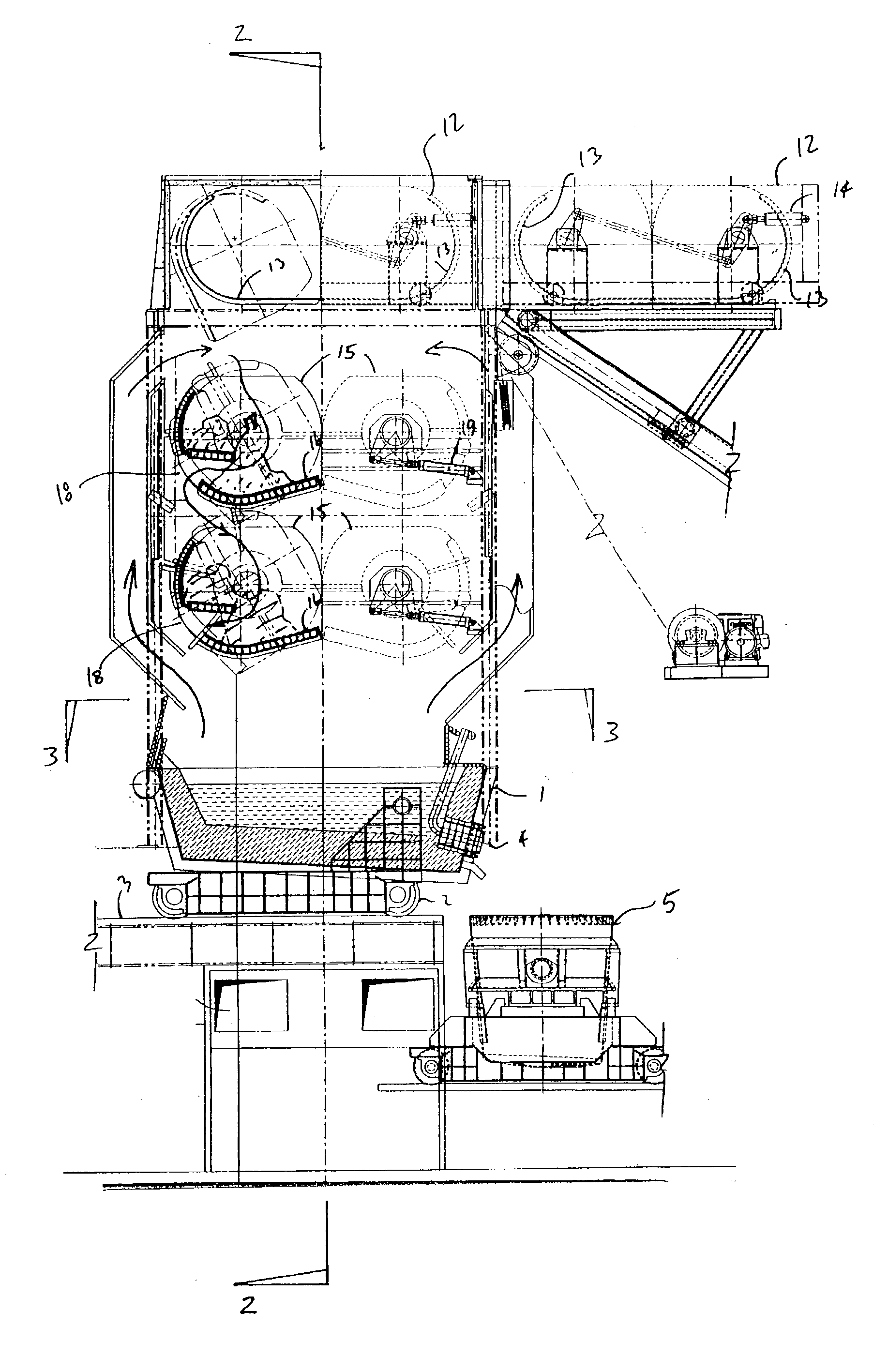
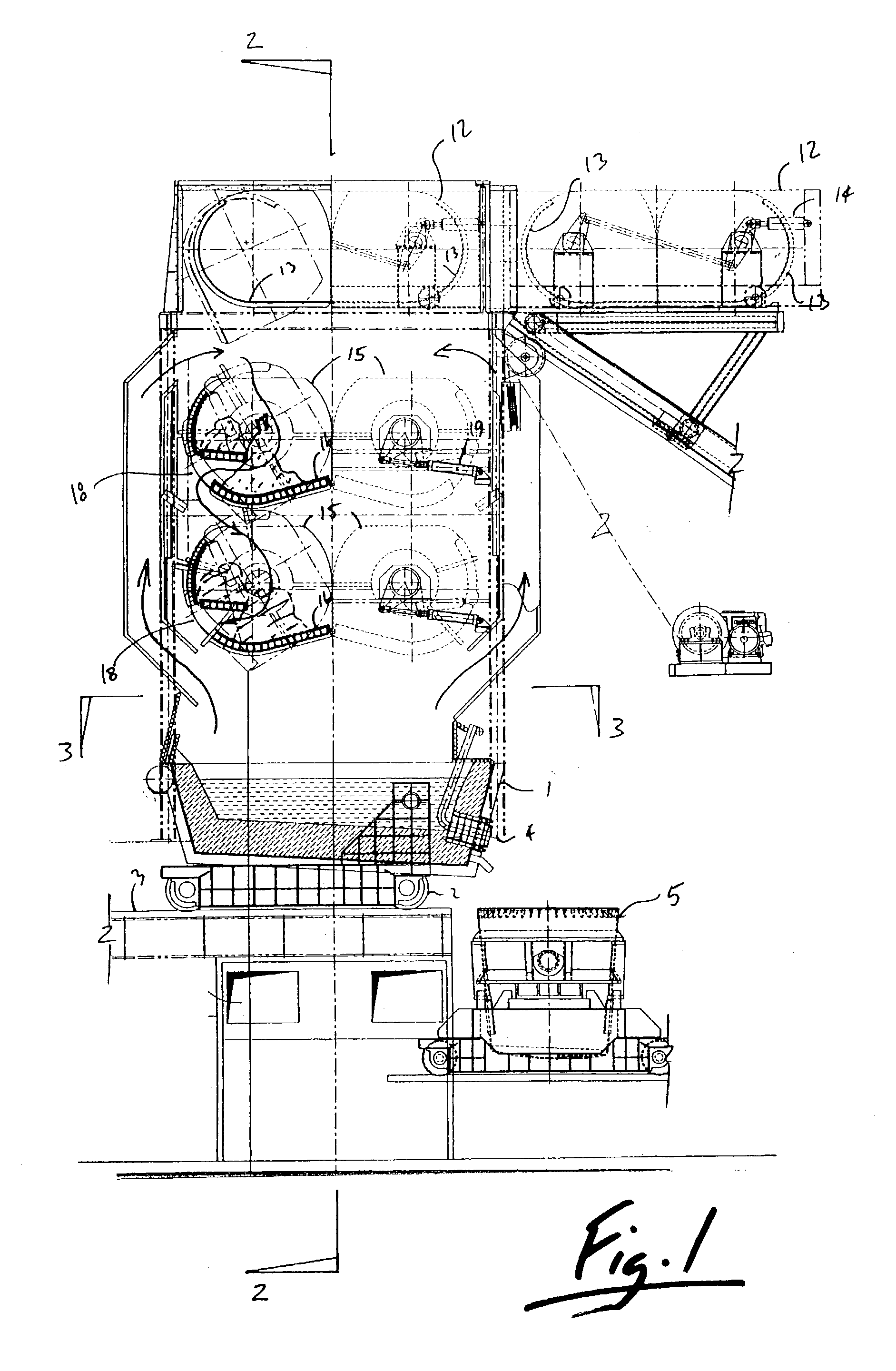
[0112] FIG. 1 illustrates an embodiment of a metallurgical furnace with tilting vessel 1 mounted on a transfer car 2 that rolls on rails 3 and can be inserted and withdrawn from the furnace structure if desired for repair or replacement. In FIG. 1 the vessel 1is shown with a full load of molten metal, ready for tapping through the horizontally oriented taphole 4 into the molten steel / metal transfer ladle 5.

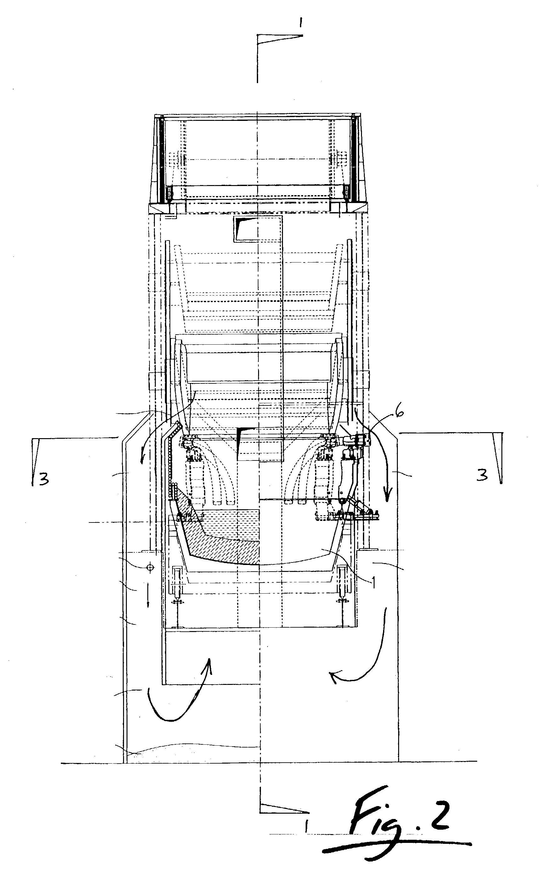
[0113] As best shown in FIG. 4 the vessel 1 and its contents are heated with four (4) retractable, generally curved oxy-fuel burners / oxygen lances 6. The oxy-fuel burners / oxygen lances 6 are rotatably inserted and withdrawn through a small opening in the sidewall of the furnace and can be easily retracted for removal of the vessel 1 along the tracks 3. The oxy-fuel burners / oxygen lances 6 need not be retracted to perform the tilting of the vessel 1 as shown in FIG. 5. and FIG. 6.

[0114] With reference to FIG. 5, the position of the vessel 1 is shown with the maximum amount of molte...


PUM

PropertyMeasurementUnit
Temperatureaaaaaaaaaa
Pressureaaaaaaaaaa
Massaaaaaaaaaa

Abstract

A Preheater-Steelmaking Furnace and closed loop Process System for semi-continuous melting of integrally preheated recycled or virgin ferrous charge, by using highly energy efficient combustion process of natural gas combusted by oxygen as the main heat source, after preheating of the cold charge, by fully exploiting thermal energies of the melting process off-gases, in a gas tight, low noise, ecologically friendly PSF with scant CO and drastically reduced CO2 in exhaust gases for semi-continuous, batch self-charging, sealed pairs of eccentrically rotating quasi cylindrical, permeable half drums hoppers creating separate preheating chambers.

Description

[0001] I. Field of the Invention[0002] This invention relates to an explicitly by oxygen combusted fossil fuel powered, primary energy highly efficient and ecologically friendly, gas-tight, low noise, metallurgical apparatus and closed circuit process system of single structure equipment assembly for semi-continuous, batch melting of adequate size cold metallic charge, preferably recycled steel scrap, DRI, HBI and other iron containing materials by utilizing only oxy-fuel thermal energy, generated by special oxy-fuel burners, after integral and gradual high temperature, low oxidation preheating of the cold metallic charge using primarily sensible and chemical thermal energy of the flue gases, augmented by special stationary oxy-fuel burners. The mechanisms of the apparatus and operating procedure of the process system are specified in claim 1 other related claims.[0003] II. Description of the Prior Art[0004] Iron and steelmaking production processes relate to the most energy intensi...

Claims


Application Information

Patent Timeline
IPC IPC(8): C21B11/08C21C5/56F27B3/06F27B3/18F27B3/22F27D3/12F27D3/15F27D5/00F27D13/00F27D17/00
CPCC21B11/08C21C5/56C21C5/565C21C2005/5276F27B3/065F27B3/18Y10S266/90F27D3/1518F27D13/002F27D17/001F27D2003/127F27D2005/0075Y10S266/901F27B3/225Y02P10/143Y02P10/20
Inventor WUNSCHE, EDGAR R.
Owner EMPCO (CANADA) LTD
Why Eureka
Try Eureka