Transmit/receiver module for active phased array antenna

a phased array antenna and transmit/receiver technology, applied in the field of radars based on active phased array antenna systems, can solve the problems of less reliability of t/r modules, large size of t/r modules, and suffers in the art, so as to reduce the size of the complete transmit/receiver module, high peak and average power output, and high power output.

Inactive Publication Date: 2003-08-21
CHIEF CONTROLLER RES & DEV MINIST OF DEFENCE GOVERNMENT OF INDIA THE
View PDF0 Cites 54 Cited by
  • Summary
  • Abstract
  • Description
  • Claims
  • Application Information

AI Technical Summary

Benefits of technology

0030] In accordance with the present invention, the improved Transmit / Receive module for Active Phased Array Antenna elements operating in L-band is realized through hybrid architecture employing both Microwave Integrated Circuit (MIC) as well as Monolithic Microwave Integrated Circuit (MMC). The use of MIC components in transmit chain of the module helped in generating high power output necessary for long ranging while incorporation of MMIC technology in receives chain of the module helps in miniaturizing the same thus reducing the size of the complete Transmit / Receive module. The proposed Transmit / Receive module can operate in entire L-band providing high peak and average power output with a very high degree of reliability and repeatability. The module is able to provide very close amplitude and phase level matching and tracking for the Transmit / Receive Modules. The Transmit Chain of the module is designed to generate a high peak power output, with a large pulse width and duty over the large RF bandwidth, using Silicon (Si) bipolar transistors operating in efficient class `C` mode. Low Noise Amplifier (LNA), Digital Attenuator and Shared Phase Shifter with T / R switches in the Receive Chain of the T / R module, use GaAs (Gallium Arsenide) MMICs for a reliable cost effective solution. Si PIN diodes having high breakdown voltage are used for realizing Receiver Protector Circuitry. The module has an integral on-mounted driver / control circuitry using a microcontroller and miniature hybrid packaging employing SMDs (Surface Mount Devices). The Transmit and Receive Chains are configured using microstrip circuitry on two soft ceramic microwave laminates, which are stacked compactly in a signal T / R module housing. The transmit circuit laminate is screwed on to the integrated liquid cooled cold plate of the module housing, which provides the best cooling efficiency by utilising microchannel cooling underneath each of the power devices of the Transmit Chain. The overall module size is compact and fits in a triangular array grid.

Problems solved by technology

However, these Transmit / Receive modules, known in the art suffer from following disadvantages.
Primary disadvantage of Transmit / Receive modules, known in the art, is that these are realized through Microwave Integrated Circuit (MIC) architecture thereby making the size of the T / R module bulky.
Another disadvantage of Transmit / Receive modules, known in the art, is that reliability of these T / R modules is less because of large number of interconnects therein.
Yet another disadvantage of Transmit / Receive modules, known in the art, is that their repeatability characteristics for phase and amplitude over all the Transmit / Receive Modules is very low.
Still further disadvantage of Transmit / Receive modules, known in the art, is that their phase and amplitude setting accuracy is inferior.
Yet another disadvantage of Transmit / Receive modules, known in the art, is that these are not cost effective.

Method used


Image

  • Transmit/receiver module for active phased array antenna
  • Transmit/receiver module for active phased array antenna
  • Transmit/receiver module for active phased array antenna

Examples


Embodiment Construction

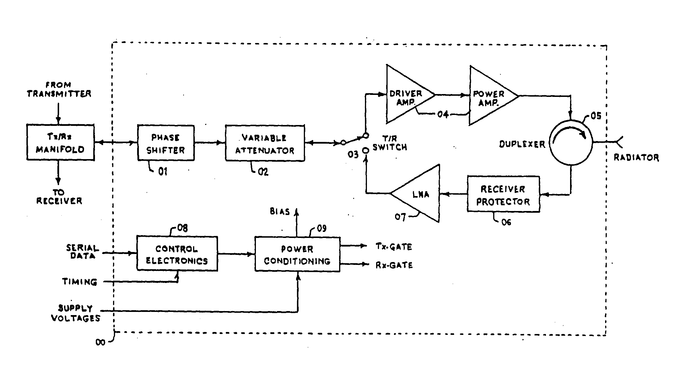
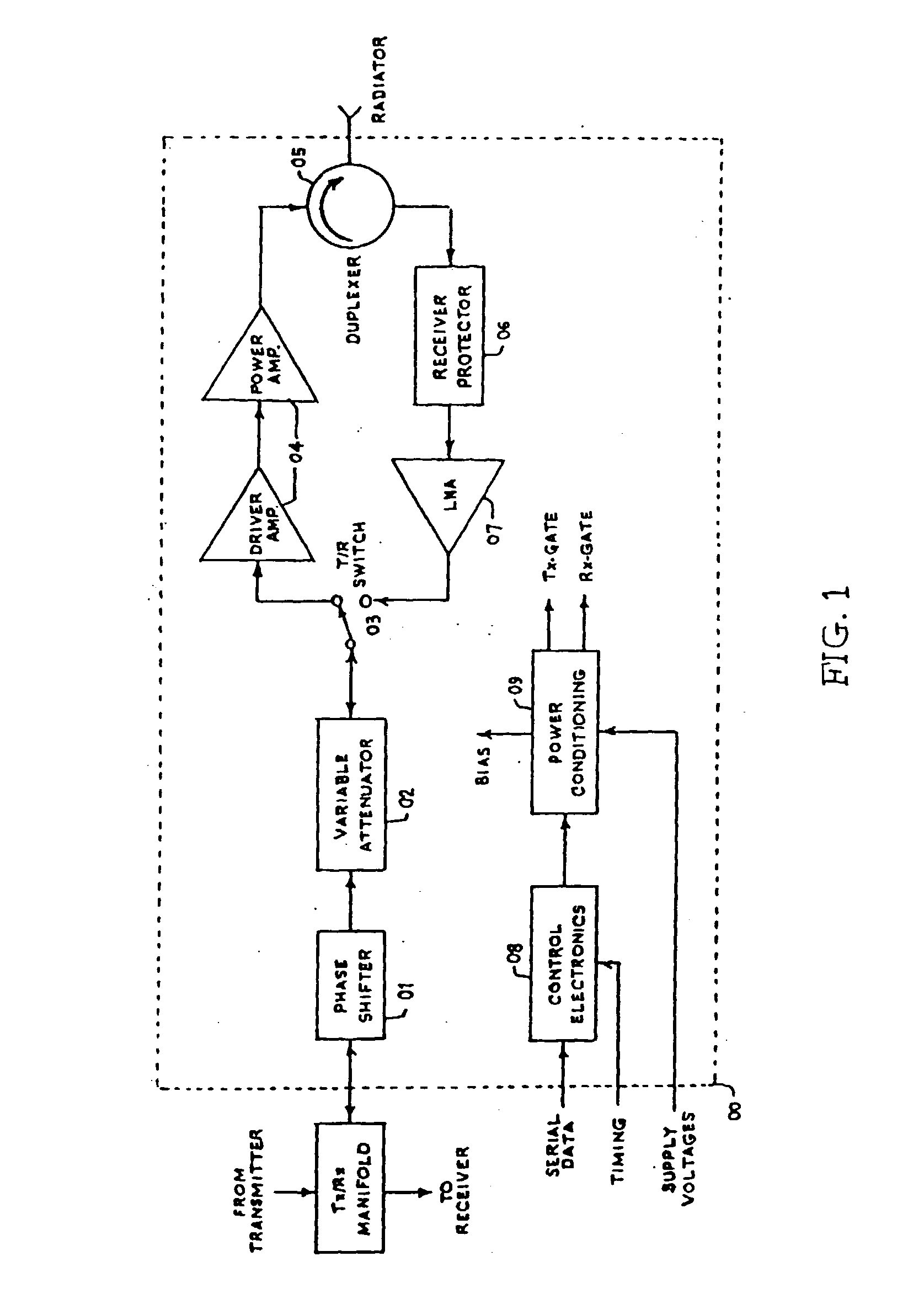
[0038] Referring to FIG. 1, T / R switch 03 is shown in the transmit mode of operation. During the transmit mode of Radar, a pulsed RF signal (Radar Exciter Output) is supplied to the module from the array manifold. This signal is phase Shifted in a digital phase shifter 01 and amplitude adjusted in digital attenuator 02 at each of the module site to produce the desired radiation beam. The signal is then amplified by transmits driver and final amplifiers 04, and routed through the circulator-duplexer 05 to the radiating element. In the receive mode, Radar return signals are routed back through the duplexer 05, the receiver protector 06 and the low noise amplifier 07 which largely establishes the system noise figure. The amplified return signal is amplitude adjusted and phase shifted in the same digital attenuator 02 and phase shifter 01 respectively and routed to the array manifold.

[0039] The amplitude weighting (through the digitally controlled attenuator 02) on the transmit and rece...


PUM


Abstract

This invention relates to a transmit and receive module for active phased array antenna system based upon a combination of hybrid microwave integrated circuit (MIC) as well as monolithic microwave integrated circuit (MMIC) technology. The module comprises a signal transmit chain having switching means (03) for switching the module to transmittance mode. Means are provided for applying pulsed RF signal to the said module from array manifold. A phase shifter (01) is connected to a digital attenuator (02) and the output of the attenuator (02) is connected to a power amplifier (04). The amplified signals from amplifier (04) are conveyed to a duplexer means (05) connected to said power amplifier (04) and for routing back the received signal through a receiver protector (06) and low noise amplifier means (07). Electronic means are connected to a power conditioner for controlling the operation of the device.

Description

[0001] This invention relates to a Transmit / Receive Module for Active Phased Array Antennas and more specifically to a Transmit / Receive module for L-Band Active Phased Array Antennas / Apertures which are employed in long range Active Phased Array Radars.PRIOR ART[0002] A Radar based on Active Phased Array Antenna System basically includes a plurality of active radiating antenna elements each of which is driven by / drives an individual Transmit / Receive module located closely adjacent thereto. Active Phased Arrays or Active Aperture Arrays, are being utilised in modern day Radar Systems. The active Array architecture overcomes the major Passive Array problems viz, low reliability inherent with tube type Radar Transmitters and their attendant high voltage power supplies and modulation, and the losses presented by their reciprocal ferrite / PIN diode phase shifters with the associated Passive Array RF manifold. Active Phased Arrays use individual solid-state T / R microwave module element at ...

Claims


Application Information

Patent Timeline
Patent Type & Authority Applications(United States)
IPC IPC(8): G01S7/03H01Q21/00
CPCH01Q21/0025G01S7/032
Inventor REVANKAR, UDAYSHANKAR KASHINATHRAOSOPHY, KALAPPURAKKAL THOMASSREENIVASULU, KILARIVEERABHADRA, KORI MALLESHAPPA
Owner CHIEF CONTROLLER RES & DEV MINIST OF DEFENCE GOVERNMENT OF INDIA THE
Why Eureka
Try Eureka