Motor driver

Inactive Publication Date: 2004-01-15
PANASONIC CORP
View PDF5 Cites 65 Cited by
  • Summary
  • Abstract
  • Description
  • Claims
  • Application Information

AI Technical Summary

Benefits of technology

0011] The present invention addresses the problems discussed above and aims to provide a motor driver that can drive a motor at an optimal efficiency in any conditions with lower torque ripples, fewer vibrations, and lower noises. This motor driver

Problems solved by technology

However, an inductance component of driving coils positively generates a phase delay in the phase current, so that the foregoing phase difference is produced.
This method is conceivable; however, an amount

Method used


Image

  • Motor driver
  • Motor driver
  • Motor driver

Examples


exemplary embodiment 1

[0045] Exemplary Embodiment 1

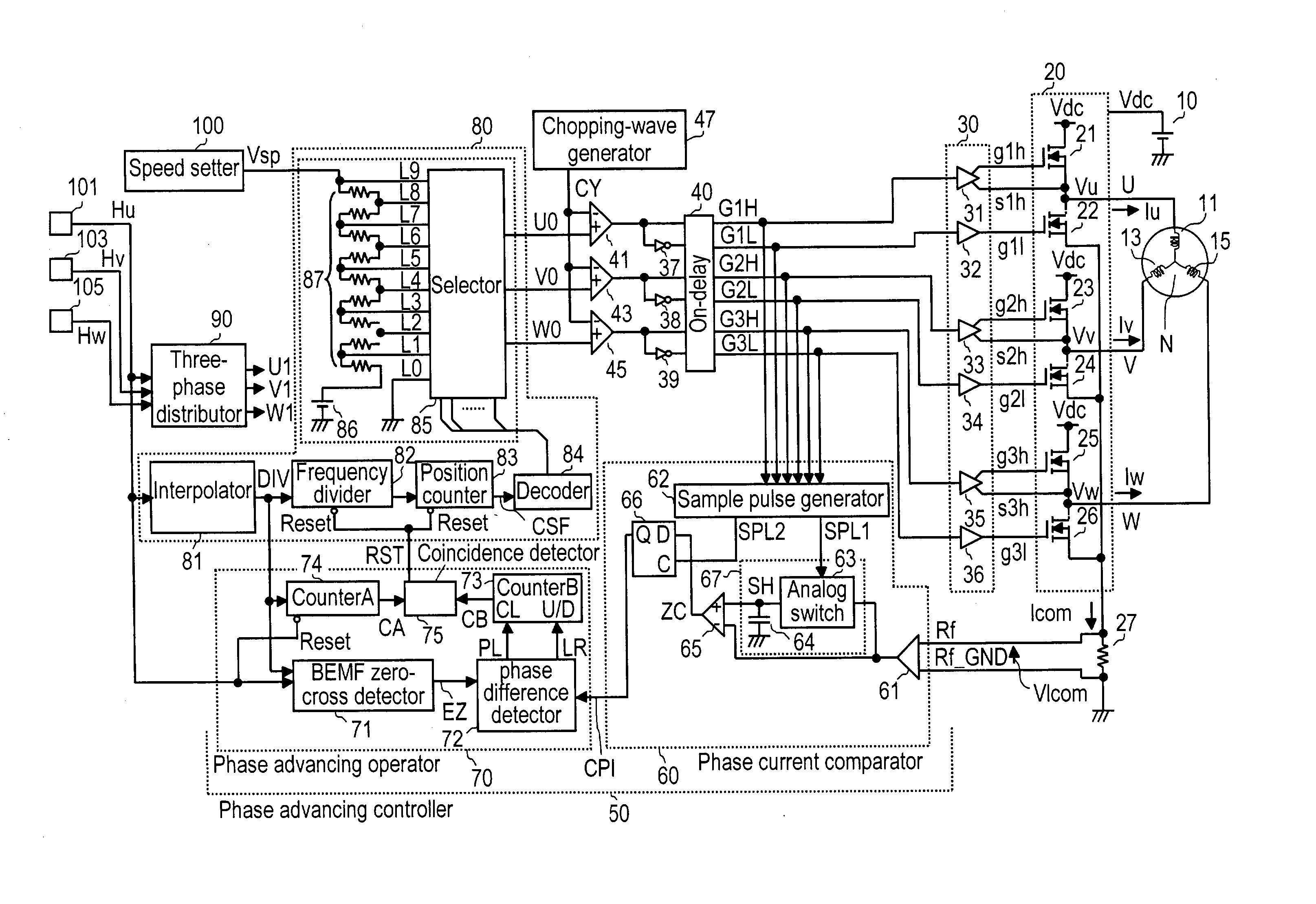
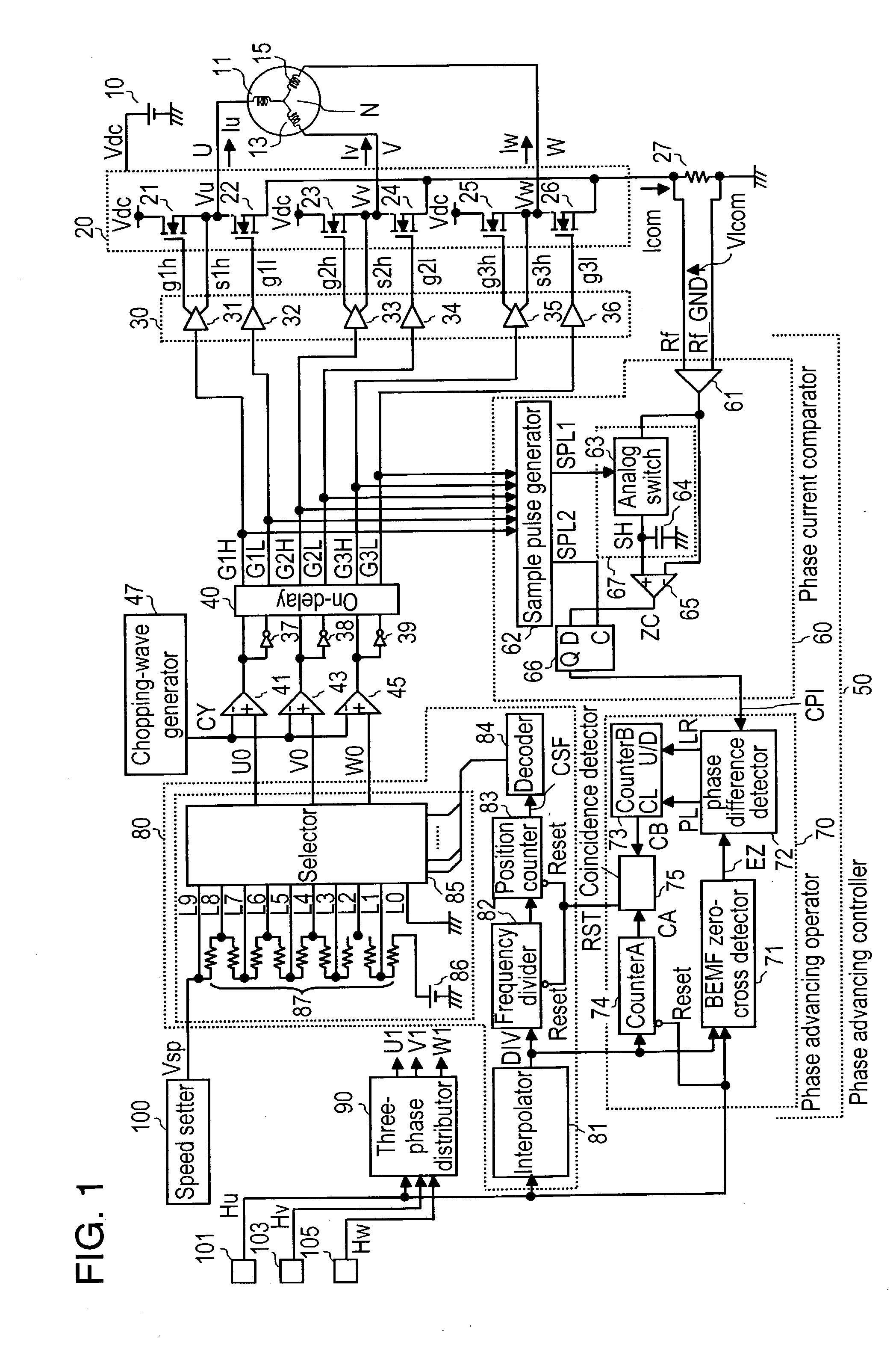
[0046] In FIG. 1, driving coils 11, 13 and 15 of the three phases (U, V, W) are coupled to power feeder 20 in the following way: Power feeder 20 forms an upper arm using field effect transistors (FETs) 21, 23 and 25, and forms a lower arm using FETs 22, 24 and 26. A first terminal of coil 11 of phase U is coupled to a junction of FET 21 and FET 22, a first terminal of coil 13 of phase V is coupled to a junction of FET 23 and FET 24, and a first terminal of coil 15 of phase W is coupled to a junction of FET 25 and FET 26. Second terminals of coils 11, 13 and 15 of phase U, V and W are coupled to each other, thereby forming neutral point N.

[0047] Direct-current power supply 10 connects its positive feeder terminal to power feeder 20, thereby powering the three-phase coils via power feeder 20. On a line between the negative feeder terminal of power supply 10 and power feeder 20, common-current detecting resistor 27 is placed for detecting common-current "Ic...

exemplary embodiment 2

[0125] Exemplary Embodiment 2

[0126] FIG. 15 illustrates an outdoor unit of an air conditioner using a fan motor employing the motor driver of the present invention. In FIG. 15, outdoor unit 201 is partitioned into compressor room 206 and heat exchanging room 209 by partition 204 vertically disposed on bottom plate 202. Compressor 205 is disposed in room 206, and heat exchanger 207 as well as blower fan-motor 208 is disposed in room 209. Box 210 containing electrical equipment is disposed on partition 204.

[0127] Fan motor 208 is structured by mounting a blower fan to the rotary shaft of a brush-less DC motor. Fan motor 208 is driven by a motor driver housed in box 210. Fan motor 208 spins to rotate the blower fan, and the wind from the fan cools heat exchanging room 209.

[0128] Motor driver 203 in accordance with the first embodiment can be used in this second embodiment. Therefore, the alternating current (preferably a sine wave current) changing consecutively runs through the motor ...

exemplary embodiment 3

[0133] Exemplary Embodiment 3

[0134] FIG. 16 shows a structure of an inkjet printer which employs the motor driver of the present invention in a driving system. In FIG. 16, inkjet printer (hereinafter referred to simply as a printer) 310 employs, in the driving system, carriage motor 301 for scanning print-head 307 mounted to a carriage and paper-feeding motor 306 for feeding recording paper. Carriage motor 301 is a brush-less DC motor and driven by motor driver 300. Paper feeding motor 306 is a stepping motor.

[0135] When paper feeding motor 306 spins, its torque is delivered to paper feeding roller 305, which feeds recording paper 308 this side in FIG. 16. On the other hand, pulley 302 is mounted to a rotary shaft of carriage motor 301, and timing belt 303 is entrained about pulley 302, and print head 307 is mounted to belt 303. Head 307 ejects liquid ink through nozzles (not shown) onto recording paper 308. Rotation of the carriage motor in forward and reverse directions allows, vi...


PUM


Abstract

In a motor driver, based on driving waveforms of respective phases generated by a driving waveform generator, a power feeder feeds respective phase-coils with an alternating current consecutively changing in sine wave. Further, a phase advancing controller adjusts phases of the driving waveform, and performs phase-advancing control such that each phase of back electromotive forces induced in respective phase-coils generally coincides with a phase of the ac running through the coils. In phase-advancing controlling, a phase current is detected with a common current. The structure discussed above can reduce torque ripples, vibrations and noises, and a motor thus can be driven efficiently.

Description

[0001] The present invention relates to a motor driver suitable for driving a brush-less dc motor used in an air conditioner, a water heater equipped with a combustion fan motor, an air cleaner, and information apparatuses such as a copying machine and a printer. More particularly, it relates to a motor driver that feeds motor driving coils with an alternating current consecutively varying, more preferably an approx. sine-wave current. The flow of the ac makes a phase difference generally zero between a phase of the back electromotive forces induced in those coils and a phase of the ac running through those coils. As a result, a motor of lower torque ripples, fewer vibrations, and lower noises is obtainable.[0002] DC brushless motors have been widely used as driving motors built in, e.g., an air conditioner and an information apparatus including a copying machine, a printer and the like because of the advantages of the motors such as a long service-life, high reliability, and easine...

Claims


Application Information

Patent Timeline
IPC IPC(8): H02P6/06H02P6/14H02P6/08H02P6/10H02P6/15H02P6/28
CPCH02P6/145H02P6/10H02P6/153
Inventor YASOHARA, MASAHIROSUGIURA, KENJI
Owner PANASONIC CORP
Why Eureka
Try Eureka