High-purity fluorine gas, production and use thereof, and method for analyzing trace impurities in high-purity fluorine gas

a high-purity fluorine gas and trace impurity technology, applied in the field of high-purity fluorine gas, production and use thereof, and the method of analyzing trace impurities in high-purity fluorine gas, can solve the problems of difficult handling of fluorine gas, analysis methods that cannot be optimal methods, and the scarce market value of fluorine gas on a commercial basis. achieve the effect of reducing corrosion resistan

Inactive Publication Date: 2004-02-12
SHOWA DENKO KK
View PDF8 Cites 25 Cited by
  • Summary
  • Abstract
  • Description
  • Claims
  • Application Information

AI Technical Summary

Benefits of technology

0082] The analysis of trace impurities in a highly reactive gas such as fluorine gas can be first attained when the construction materials of the container, valve, pipeline, equipment and the like used therefor are carefully examined. In the analysis method of the present invention, a fluorinated layer is formed on the surface of a metal material or nickel film which comes into contact with a fluorine gas, whereby the problem of contamination by HF or O.sub.2, generated due to H.sub.2O and the like adsorbed to the inner surface of a material coming into contact with a fluorine gas at the time of analysis, can be solved.
0083] Each part (valve, container for filling fluorine gas-removing and separating agent, pipeline, pressure gauge) which comes into contact with a fluorine gas is baked under heating at 200 to 300.degree. C., in the case where the construction material is, for example, a stainless steel, after applying nickel plating and in the case of nickel o

Problems solved by technology

A fluorine gas is a combustion-supporting gas having strong oxidative property and also has strong toxicity and corrosiveness and therefore, in Japan, fluorine gas is scarcely traded on a commercial base except in a special case.
However, these analysis methods cannot be an optimal method as the analysis method for a high-purity fluorine gas, containing trace impurities in a concentration of hundreds of vol. ppm or less, even though such high-purity fluorine gas is an important key technology for the development of semiconductor industry.
Fluorine gas is difficult to handle because it is highly reactive (oxidative) and in turn highly corrosive.
Therefore, fluorine gas cannot be introduced directly into an analyzer.
Even in the case of gas chromatography which is effective for analyzing the composition of gas components, almost no method has been heretofore known for the analysis of trace impurities in a fluorine gas, because, for example, there is no appropriate separation

Method used


Image

  • High-purity fluorine gas, production and use thereof, and method for analyzing trace impurities in high-purity fluorine gas
  • High-purity fluorine gas, production and use thereof, and method for analyzing trace impurities in high-purity fluorine gas
  • High-purity fluorine gas, production and use thereof, and method for analyzing trace impurities in high-purity fluorine gas

Examples


example 2

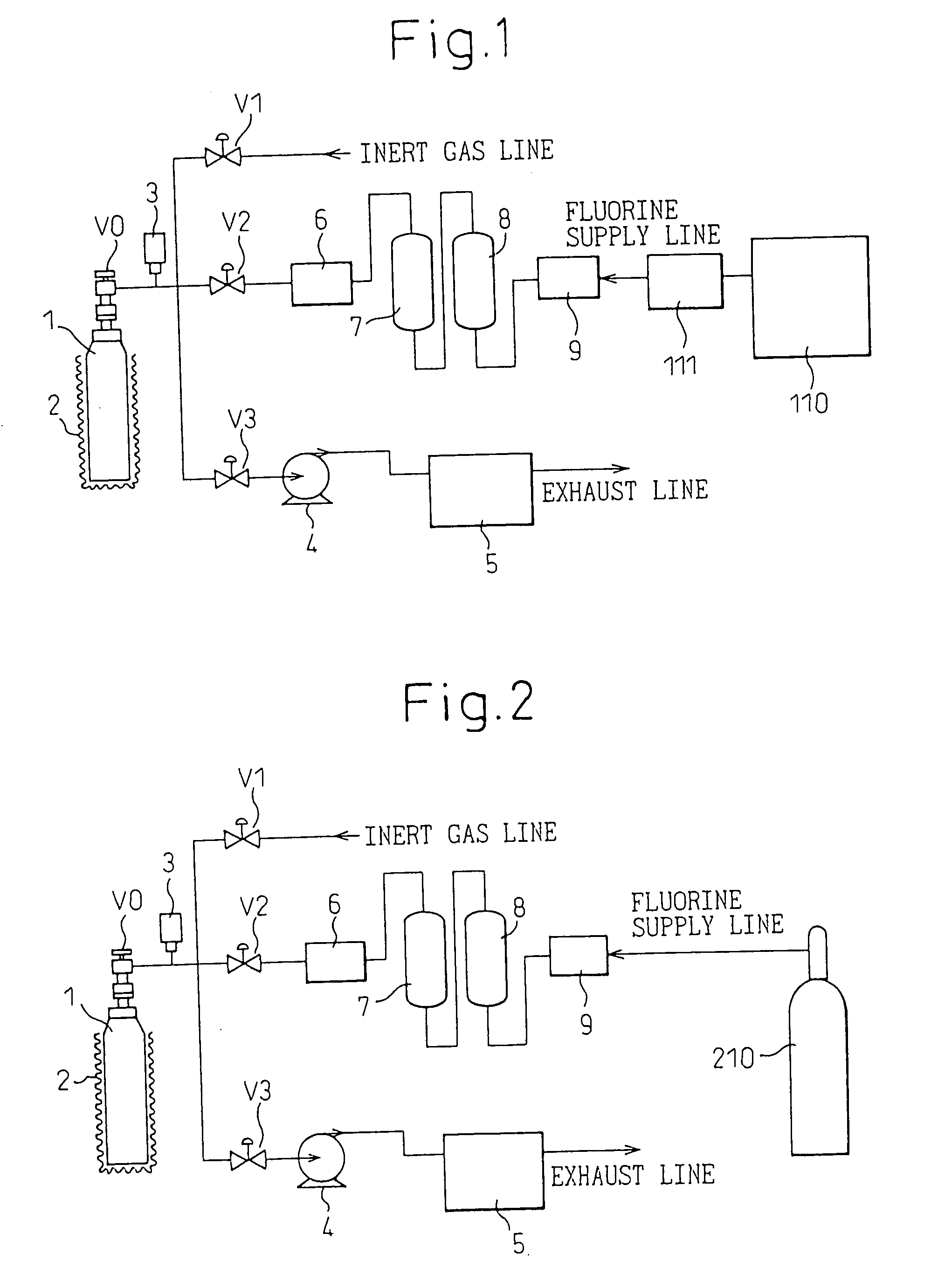
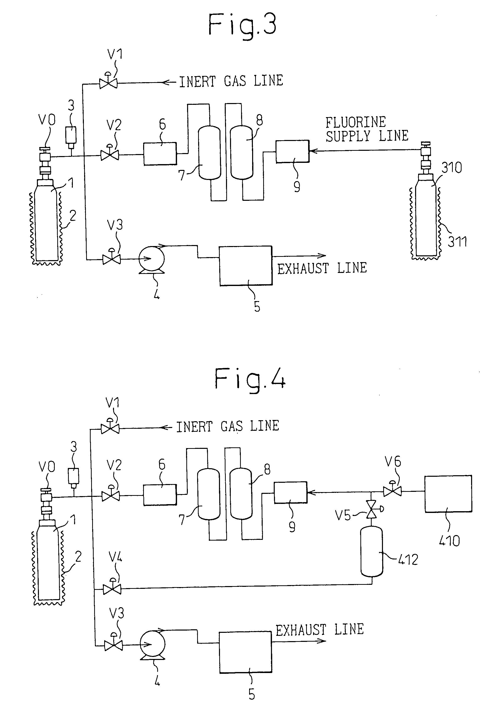
[0100] The fluorine generator 1 used in Example 1 was kept at a temperature of 350.degree. C. and the generated fluorine was split into a previously vacuumized fluorine tank 412. Then, by closing the valve 4 and opening the valve 3, the fluorine occluded into the fluoronickel compound in the fluorine generator 1 was exhausted by a vacuum pump while heating at 350.degree. C. to render the fluoronickel compound to be in a K.sub.3NiF.sub.6 state. The fluorine generator 1 was further continuously depressurized by a vacuum pump and under reduced pressure of 0.001 MPa (absolute pressure), heated at 400.degree. C. for 10 hours. Subsequently, a fluorine gas was passed from the fluorine tank 412 to a column 8 filled with sodium fluoride (NaF) at a flow rate of 100 ml / min and the crudely purified fluorine, after the removal of HF, was supplied at 250.degree. C. to the fluorine generator 1 through a tank 7.

[0101] The supply of fluorine gas was stopped, the temperature of heating the fluorine g...

example 3

[0102] In order to further reduce the impurity gases, subsequently to Example 2, the fluorine generator 1 was heated at 250.degree. C. for 1 hour under reduced pressure of 0.001 MPa (absolute pressure). Thereafter, the exhaustion by a vacuum pump was stopped and the heating temperature was elevated to 350.degree. C. to obtain a fluorine gas. This fluorine gas was designated as Fluorine Gas (Example 3) and the analysis values thereof are shown in Table 1.

1 TABLE 1 Purity Concentration of Impurities [vol ppm] [vol %] HF O.sub.2 CO.sub.2 N.sub.2 CF.sub.4 SiF.sub.4 Example 1 99.81 550 1100 100 100 10 10 Example 2 99.95 100 300 20 20 5 5 Example 3 >99.99 20 <10 <10 <10 <1 <1

example 4

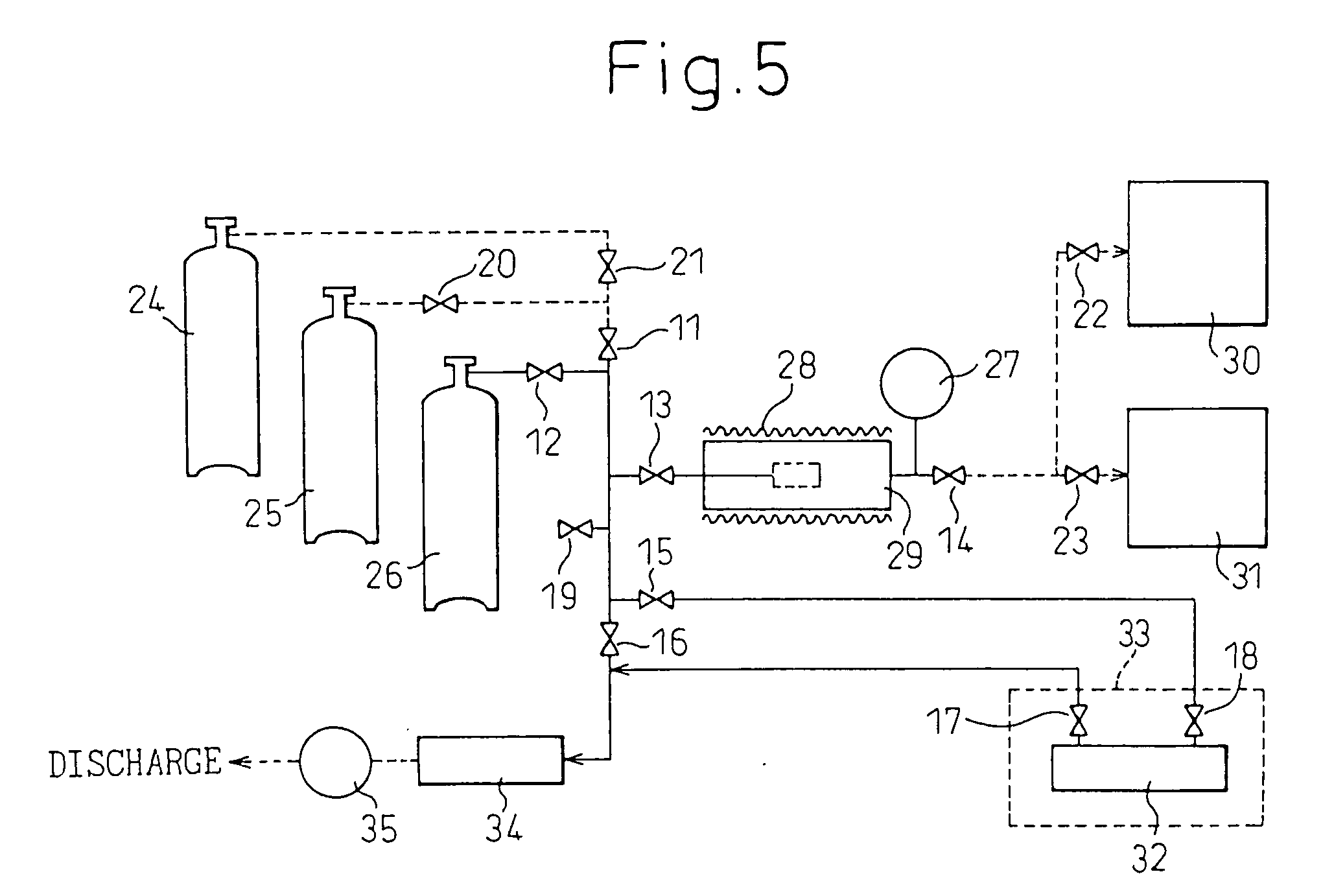
[0103] In an apparatus, shown in FIG. 5, for use in the analysis method of the present invention, each metal part of pipelines, valves 11 to 19, a pressure gauge 27, a container 29 (content volume: 500 ml), a cell 32 for FTIR and a harm-removing cylinder 34 (content volume: 3 liters), which comes into contact with a fluorine gas, was subjected to nickel plating (film thickness: 5 to 10 .ANG.). These equipments and materials were placed in an electric furnace capable of pressure reduction, baked at a temperature of 350.degree. C. under reduced pressure and cooled. The pressure inside the electric furnace was again reduced and 10% F.sub.2 diluted with N.sub.2 gas was filled to an atmospheric pressure. Thereafter, the temperature was elevated to 350.degree. C. at a temperature rising rate of 100.degree. C. / hour and the inside of the electric furnace was kept at 350.degree. C. for 12 hours to allow the fluorination to proceed.

[0104] In this surface-treated container 29, 500 g of dried K...


PUM


Abstract

A step (1) of heating a fluoronickel compound to release a fluorine gas, a step (2) of allowing a fluorine gas to be occluded into a fluorinated compound, and a step (3) of heating the fluoronickel compound and reducing an inner pressure are conducted in a container, respectively, at least once, and thereafter a high-purity fluorine gas is obtained in the step (1). Also, a step (5) of heating a fluoronickel compound and reducing an inner pressure and a step (6) of allowing a fluorine gas reduced in a hydrogen fluoride content to be occluded into the fluoronickel compound are conducted in a container having a fluorinated layer formed on its surface, respectively, at least once, the step (5) is further conducted, and thereafter a fluorine gas containing impurity gases is contacted with the fluoronickel compound to fix and remove the fluorine gas, and the impurities are analyzed by gas chromatography.

Description

[0001] This application is an application filed under 35 U.S.C. .sctn.111(a) claiming benefit pursuant to 35 U.S.C. .sctn.119(e)(1) of the filing date of the Provisional Application No. 60 / 306,421 filed Jul. 20, 2001, and the filing date of the Provisional Application No. 60 / 306,422 filed Jul. 20, 2001, pursuant to 35 U.S.C. .sctn.111(b).[0002] The present invention relates to a high-purity fluorine gas, the production and use thereof, and a method for analyzing trace impurities in a high-purity fluorine gas. Particularly, the present invention relates to a process for producing a high-purity fluorine gas, a high-purity fluorine gas and a high-purity fluoronickel compound obtained thereby, and the use of the high-purity fluorine gas, and further relates to a method for analyzing trace impurities in a high-purity fluorine gas.[0003] A fluorine gas is a combustion-supporting gas having strong oxidative property and also has strong toxicity and corrosiveness and therefore, in Japan, fl...

Claims


Application Information

Patent Timeline
IPC IPC(8): C01B7/20G01N21/03G01N21/09G01N21/35G01N30/14H01S3/036H01S3/225
CPCC01B7/20G01N21/0303G01N21/09Y10T436/19G01N2030/143H01S3/036H01S3/225G01N21/3504
Inventor TORISU, JUNICHIATOBE, HITOSHIHOSHINO, YASUYUKI
Owner SHOWA DENKO KK
Why Eureka
Try Eureka