Visual-servoing optical microscopy

Inactive Publication Date: 2004-02-12
RGT UNIV OF CALIFORNIA
View PDF3 Cites 138 Cited by
  • Summary
  • Abstract
  • Description
  • Claims
  • Application Information

AI Technical Summary

Benefits of technology

0068] Thus, the present invention provides methods and devices for the knowledge-based discovery and optimization of differences between cell types. In particular, the present invention provides visual servoing optical microscopy as described above, as well as analysis methods. The present invention provides means for the close monitoring of hundreds of individual, living cells over time; quantification of dynamic physiological responses in multiple channels; real-time digital image segmentation and analysis; intelligent, repetitive computer-applied cell stress and cell stimulation; and the ability to return to the same field of cells for long-term studies and observation. The present invention further provides means to optimize culture conditions for specific subpopulations of cells.
0069] Prior to the development of the present invention, it was technically difficult to digitally image large numbers of single living cells under a microscope. It was also difficult to simultaneously monitor multiple physiological responses in large numbers of single, living cells for an extended period of time without harming the cells. The first limitation existed largely because of the limited field of view at any given magnification. The field of view was further restricted by the limited size and resolution of the solid-state digital imaging device (i.e., charge-coupled device; CCD) inside the digital camera used. The present invention overcomes these limitations by facilitating the rapid, automatic, and repetitive monitoring of multiple fields of view (i.e., larger numbers of cells) by software control of an x,y,z microscope stage. The presen

Problems solved by technology

Moreover, this process can take place repeatedly on hundreds or thousands of cells, and human beings are not part of this coupled and automated system.
Such stimulations, p

Method used


Image

  • Visual-servoing optical microscopy
  • Visual-servoing optical microscopy
  • Visual-servoing optical microscopy

Examples


example 2

[0259] Use of VSOM

[0260] In this Example, the equipment and other aspects of the VSOM of the present invention are described.

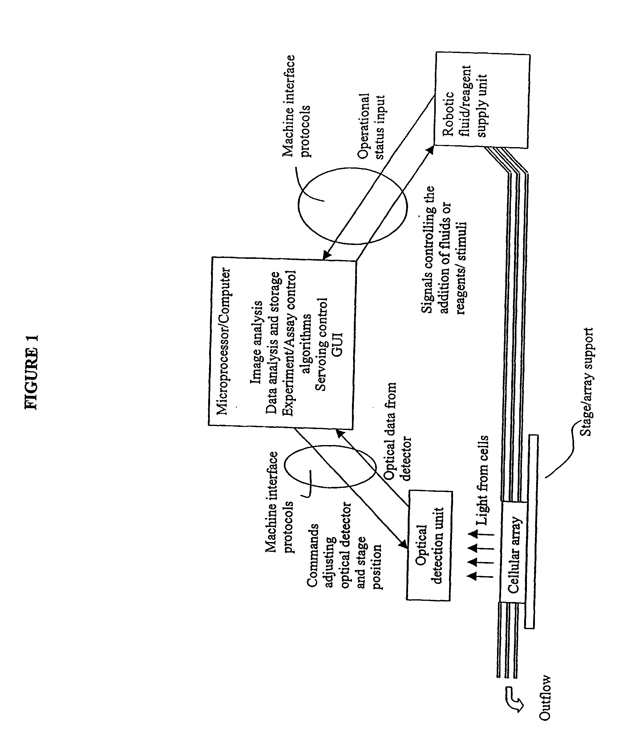
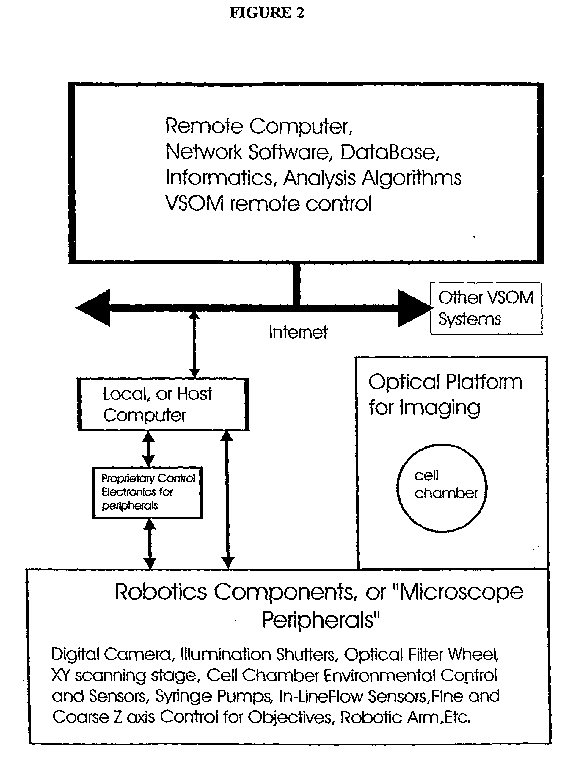
[0261] A. VSOM System Optical Platform

[0262] In most embodiments, a VSOM system is built around an inverted (i.e., the objective lens points upwards) fluorescence microscope because cell chambers and cell vessels are typically easier to design when the microscope has this geometry. However, cell chambers do exist that can be used with upright microscopes (where the objective lens points downwards). The VSOM of the present invention is suitable for use with such an optical platform. Biological research grade fluorescence microscopes are preferred, where the microscope has sufficient weight to be stable once the camera and microscope peripherals are mounted on the microscope. A standard 10.times. objective is sufficient for some VSOM experiments. Research grade microscopes, objectives and various peripherals are made by various manufacturers, including Carl Zeis...

example 3

[0279] VSOM Experiment

[0280] In this Example, a VSOM experiment conducted as described in Example 2 is described, with the indicated modifications.

[0281] The optical platform used was a Zeiss Axiovert 135 H / DIC, TV inverted microscope equipped for transmitted light (phase and DIC) and multi-color fluorescence microscopy. It was equipped with a computer-controlled xy scanning stage, z-axis stepping motor, and a six-position filter wheel (LUDL Electronic Products, Ltd. Hawthorne, N.Y.). A 12-bit Xillix CCD camera (Xillix Technologies, Vancouver, BC) containing a Kodak KAF-1400 CCD chip (1317.times.1035 pixels, 7.times.7 micron pixel size) was used for these studies. This camera has a readout rate of 8 MHz (i.e., approximately four full size images per set). Images from the camera were directly read out into the host computer, which was a Sparcstation Ultra 1, a multi-tasking UNIX workstation.

[0282] In addition, a Peltier temperature-controlled microperfusion chamber (PDMI-2 open chamb...

example 4

[0286] MDR Assay--Test Kit and VSOM Experiment

[0287] The MDR Assay .beta.-Test kit was also tested in a VSOM experiment, as described herein. FIG. 11 provides a schematic diagram of this VSOM experiment. Pumps are turned on and off at specified flow rates according to a pre-programmed recipe, or based on real-time analysis of individual cell responses. The CAM, V, and MK concentrations used are noted in the figure. The three exposures to CAM were 900 seconds (20 min) each, and thus the total exposure to CAM was 60 min. The black windows at the bottom of the Figure show the mean response of all cells in the field of view. This mean response plot is displayed on the computer screen during the VSOM experiment, and digital images from one or more channels (transmitted light is usually one of the channels displayed) are displayed on the screen as well.

[0288] The plot and images were continuously refreshed and updated during the experiment. In the two plots recorded for MCF-7 (DS, run #1)...


PUM


Abstract

The present invention provides methods and devices for the knowledge-based discovery and optimization of differences between cell types. In particular, the present invention provides visual servoing optical microscopy, as well as analysis methods. The present invention provides means for the close monitoring of hundreds of individual, living cells over time: quantification of dynamic physiological responses in multiple channels; real-time digital image segmentation and analysis; intelligent, repetitive computer-applied cell stress and cell stimulation; and the ability to return to the same field of cells for long-term studies and observation. The present invention further provides means to optimize culture conditions for specific subpopulations of cells.

Description

[0001] The present application claims the benefit of U.S. Provisional Application No. 60 / 210,543, filed Jun. 8, 2000, and U.S. Provisional Application No. 60 / 290,755, filed May 14, 2001.[0003] The present invention provides methods and devices for the knowledge-based discovery and optimization of differences between cell types. In particular, the present invention provides visual servoing optical microscopy, as well as analysis methods. The present invention further provides means to optimize culture conditions for specific subpopulations of cells.[0004] The current trend in telepresence research is to bring experts and facilities together from geographically dispersed locations (Hadida-Hassan et al., J. Struct. Biol., 125:229-234 [1999]; Parvin et al., "Visual Servoing for On-Line Facilities," IEEE Computer Mag., pages 56-62 [1997]; Potter et al., UltraMicros., 77:153-161 [1999]; Young et al., J. Supercomputer Appl. High Perf. Comput, pp. 170-181 [1996]; and Parvin et al., "A Colla...

Claims


Application Information

Patent Timeline
IPC IPC(8): G01N15/14G06T7/00
CPCG01N15/1475G06K9/0014G06K9/4609G06T7/0012C12M41/46G06T2207/10056G06T2207/20081G06T2207/30024C12M35/08G06T7/403G06T7/44G06V20/695G06V10/443
Inventor CALLAHAN, DANIEL E.PARVIN, BAHRAM
Owner RGT UNIV OF CALIFORNIA
Why Eureka
Try Eureka