Thermoplastic elastomeric foam materials and methods of forming the same

Inactive Publication Date: 2004-02-26
MUCELL EXTRUSION
View PDF6 Cites 57 Cited by
  • Summary
  • Abstract
  • Description
  • Claims
  • Application Information

AI Technical Summary

Benefits of technology

0079] The function and advantage of these and other embodiments of the present invention will be more fully understood from the examples below.

Problems solved by technology

Under other, typically more violent foaming conditions, the cells rupture or become interconnected and an open-cell material results.
The number of voids or cells per unit volume of material typically is relatively low according to that technique and often the material exhibits a non-uniform distribution of cells throughout the material.
The stream is rapidly heated, and the resulting thermodynamic instability (solubility change) creates sites of nucleation, while the system is maintained under pressure preventing significant growth of cells.
However, TPE foams, and especially low density TPE foams, may absorb water and, thus, may have limited use in these applications.
First, where a TPE includes viscosity reducers such as mineral oils, the viscosity reduction results

Method used


Image

  • Thermoplastic elastomeric foam materials and methods of forming the same
  • Thermoplastic elastomeric foam materials and methods of forming the same
  • Thermoplastic elastomeric foam materials and methods of forming the same

Examples


examples 2-13

Extruded Product using Nitrogen as Blowing Agent

[0095] See procedure for Example 1. The material and process condition differences between the Examples are given in Table 1 below. The properties of the resultant extruded foam product are given in Table 2.

1TABLE 1 Process Conditions for Examples using Nitrogen as Blowing Agent Exit Gap Exit Taper Output Tm N2 Example Material in Angle deg lb / hr deg F. Level 1 Santoprene 201-73 0.028 14 66 329 0.32 2 Santoprene 201-73 0.028 0 67 327 0.33 3 Santoprene 201-73 0.028 6 92 340 0.30 4 Santoprene 201-73 0.028 6 88 341 0.41 5 Santoprene 201-73 0.028 6 88 341 0.50 6 Santoprene 201-68W 0.028 6 100 339 0.25 7 Santoprene 201-68W 0.028 6 97 339 0.25 8 Santoprene 121-68W 0.028 6 101 337 0.39 9 Santoprene 121-68W 0.028 6 101 336 0.40 10 Sarlink X8168 0.021 6 100 327 0.40 11 Sarlink X8168 0.028 6 100 325 0.30 12 Uniprene 7100-64 0.028 6 100 331 0.16 13 Uniprene 7100-64 0.028 6 100 319 0.28

[0096]

2TABLE 2 Foam Properties for Examples using Nitrogen as ...

example 14

Extruded Product using Carbon Dioxide as Blowing Agent

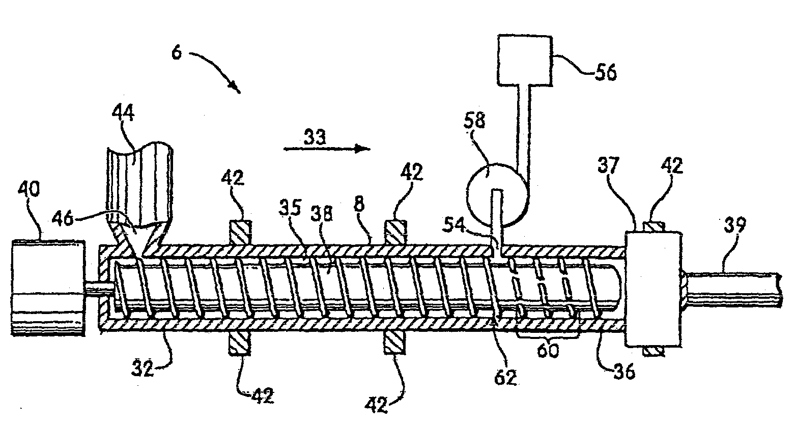
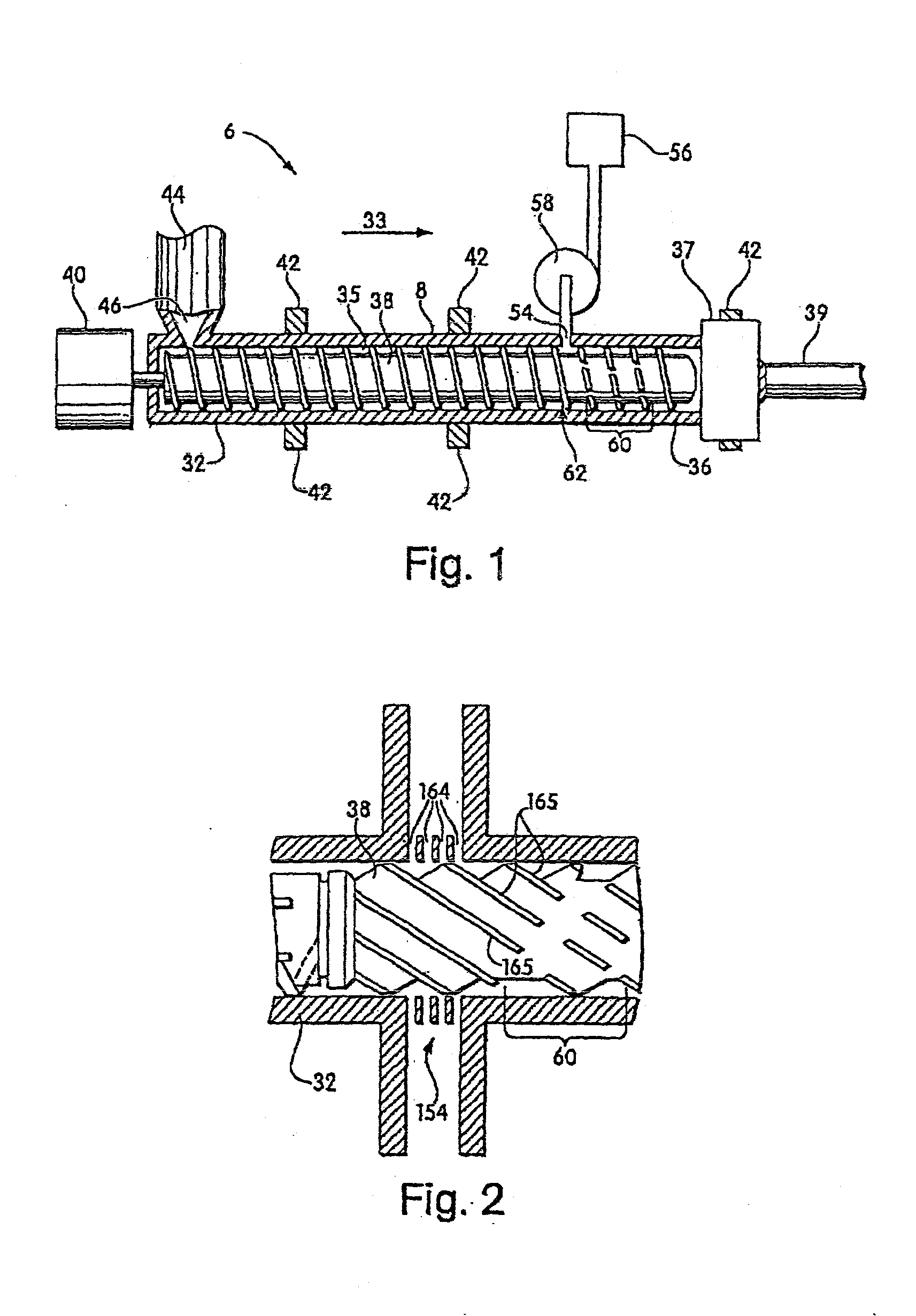
[0104] Extrusion Equipment: A line for the production of extruded profiles was assembled employing a 60 mm diameter, 34:1 L:D single screw extruder (Krauss-Maffei, Munich, Germany). An injection system for the injection of CO.sub.2 into the extruder was placed at approximately 20D diameters from the feed throat of the extruder. The injection system included 2 equally spaced circumferential, radially-positioned ports, each port including 176 orifices, each orifice of 0.020 inch diameter, for a total of 352 orifices. The injection system included an air actuated control valve to precisely meter a mass flow rate of blowing agent at rates from 0.04 to 3.5 lbs / hr at pressures up to 5500 psi.

[0105] The screw of the primary extruder was a specially designed screw to provide feeding, melting and mixing of the polymer / talc concentrate followed by a mixing section for the dispersion of blowing agent in the polymer.

[0106] Connected to the e...

examples 15-20

Extruded Product using Carbon Dioxide as Blowing Agent

[0114] See procedure for Example 14. The material and process condition differences and the resultant foam properties are given in Table 4 below. Example 17 produces a TPE foam having a water absorption of greater than 40 times (1-A) / A, wherein A is the foam density in g / cc.

[0115] All other Examples produce a TPE foam having a water absorption of less than 40 times (1-A) / A, wherein A is the foam density in g / cc.

[0116] FIG. 8 graphs the water absorption vs. foam density for Examples 14-20 and Comparative Examples 1-4. The lines for water absorption at various values of C as given above and shown in FIG. 4 are also overlaid on this chart for reference.

4TABLE 4 Examples using Carbon Dioxide as Blowing Agent Tm CO2 Density Water Example Material deg F. Level % g / cc Absorption % 14 Santoprene 201-68W228 334 2.4 0.36 51 15 Santoprene 201-68W228 334 1.8 0.44 22 16 Santoprene 201-68W228 334 1.2 0.46 7 17 Santoprene 201-68W228 338 2.4 0.3...


PUM

PropertyMeasurementUnit
Timeaaaaaaaaaa
Sizeaaaaaaaaaa
Sizeaaaaaaaaaa

Abstract

Foams with low water absorption are provided, along with thermoplastic elastomeric foam materials and methods of forming the same. In some embodiments, the TPE foams have a low water absorption. Microcellular foams are included. Processing conditions (e.g., blowing agent type and content, die geometry, exit melt temperature, among others) may be controlled to produce foams having desirable characteristics, such as low water absorption.

Description

[0001] The present invention relates generally to polymeric foams, and more particularly, to thermoplastic elastomeric foam materials and methods of forming the same.BACKGROUND OF INVENTION[0002] Polymeric foam materials are well known, and typically are produced by introducing a physical blowing agent into a molten polymeric stream, mixing the blowing agent with the polymer, and extruding the mixture into the atmosphere while shaping the mixture. Exposure to atmospheric conditions causes the blowing agent to gasify, thereby forming cells in the polymer. Under some conditions the cells can be made to remain isolated, and a closed-cell foamed material results. Under other, typically more violent foaming conditions, the cells rupture or become interconnected and an open-cell material results. As an alternative to a physical blowing agent, a chemical blowing agent (CBA) can be used which undergoes chemical decomposition in the polymer material causing formation of a gas. Microcellular ...

Claims


Application Information

Patent Timeline
IPC IPC(8): C08J9/12
CPCC08J9/122B29C47/1072B29C47/0042B29C47/0004B29C48/022B29C48/0012B29C48/295Y10T428/249953Y10T428/249958C08J9/00C08J9/12
Inventor ANDERSON, JERE R.BLIZARD, KENT G.CHEN, LIQINOKAMOTO, KELVIN T.
Owner MUCELL EXTRUSION
Why Eureka
Try Eureka