
Cement composite, concrete, concrete cask and method of manufacturing concrete

a technology of cement composite and concrete, applied in the field of concrete casks, can solve the problems of prior art technology posing problems related to sealing performance, poor heat resistance of concrete casks, and accelerated corrosion of steel-made canisters

Inactive Publication Date: 2004-04-08
KOBE STEEL LTD +1
View PDF9 Cites 25 Cited by
  • Summary
  • Abstract
  • Description
  • Claims
  • Application Information

AI Technical Summary

Benefits of technology

0016] FIG. 5 is a graph showing the relationship between the compressive str

Problems solved by technology

While the technology of Publication No. 2001-305375 helps prevent concrete cracking, the concrete cask has poor heat resistance.
The external air is likely to contain corrosive substances, such as chlorides, which would accelerate corrosion of a steel-made canister.
Therefore, the concrete cask of this prior art technology tends to pose problems related to sealing performance.
This would require a complicated structure of the concrete cask and pose a risk of releasing radioactive gases in case of canister breakage.
The conventional concrete casks is made of concrete of which heat-resisting temperature is 90.degree. C. or less, so that they generally necessitate complicated structures such as the provision of through holes for ventilation.
If such through holes are made in the concrete cask, the external air goes into direct contact with the canister provided inside the cask, resulting in corrosion of the canister and accidental release of radioactive material into the environment from inside the canister.
Thus, the conventional concrete casks have a problem that their neutron-shielding performance considerably decreases when used under high-temperature conditions (100.degree. C. or above).

Method used


Image

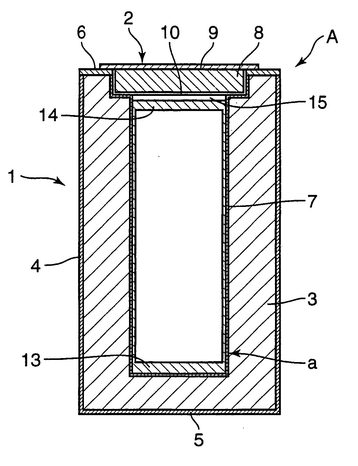
  • Cement composite, concrete, concrete cask and method of manufacturing concrete
  • Cement composite, concrete, concrete cask and method of manufacturing concrete
  • Cement composite, concrete, concrete cask and method of manufacturing concrete

Examples


experiment 1

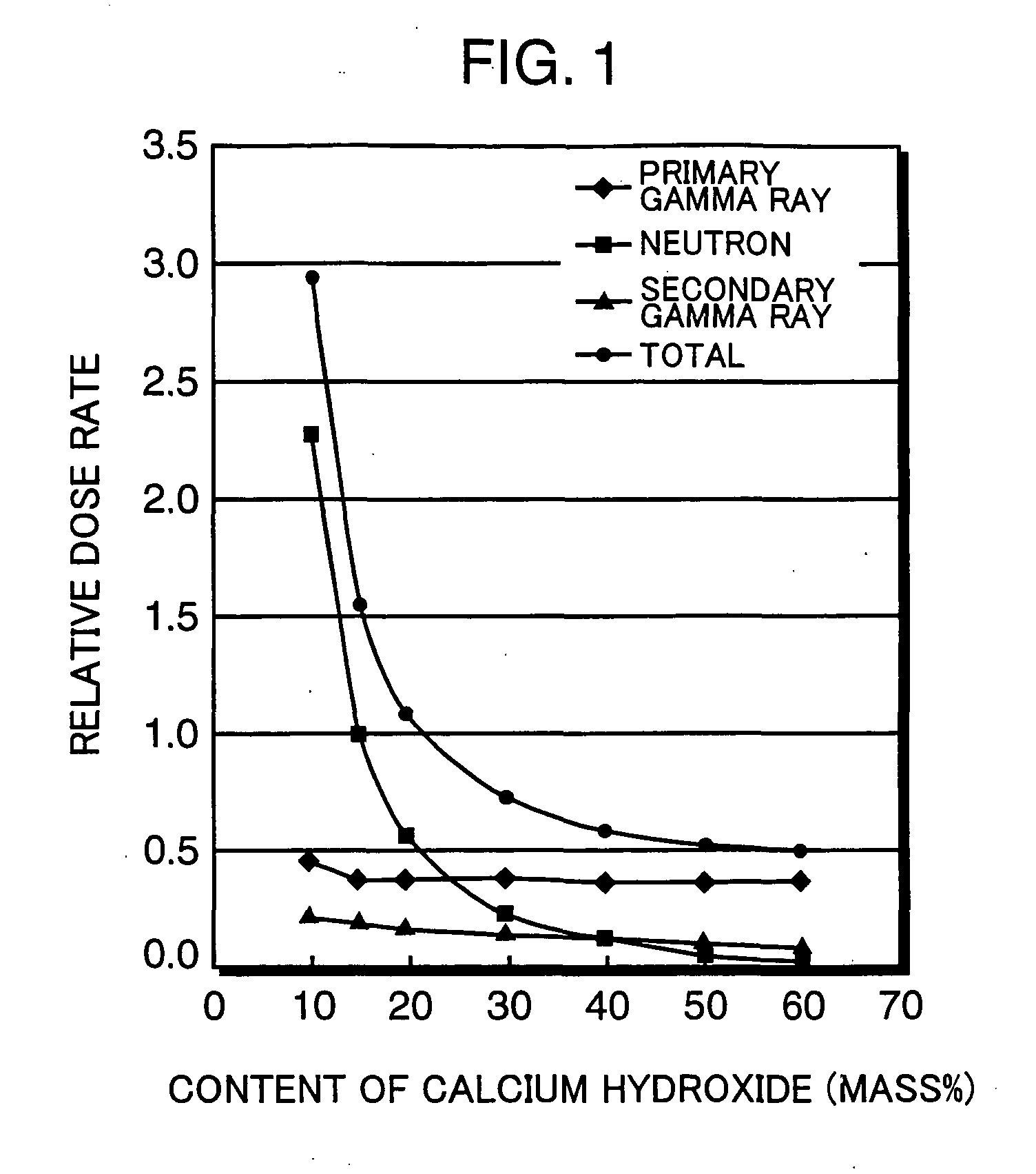
[0033] Assuming composites and concretes produced by blending appropriate quantities of Portland cement, silica fume, metallic material, chemical admixture and water and adding calcium hydroxide at various ratios, relative dose rates of the concrete cask were calculated on a simulation basis in Experiment 1. Here, the relative dose rate is defined as the ratio of dose equivalent rate at a central part of a concrete cask produced by using ordinary concrete to dose equivalent rate at a central part of a concrete cask produced by using the concrete of the invention.

[0034] FIG. 1 shows the relationship between the content of calcium hydroxide and the relative dose rate. In carrying out the simulation, an assumption was made that an iron shield was 20 cm thick, a concrete shield was 35 cm thick, the type of fuel was pressurized water reactor (PWR) fuel, burnup was 50,000 MWD / MTU, and cooling time was 10 years.

[0035] It can be seen from FIG. 1 that as the content of calcium hydroxide reac...

experiment 2

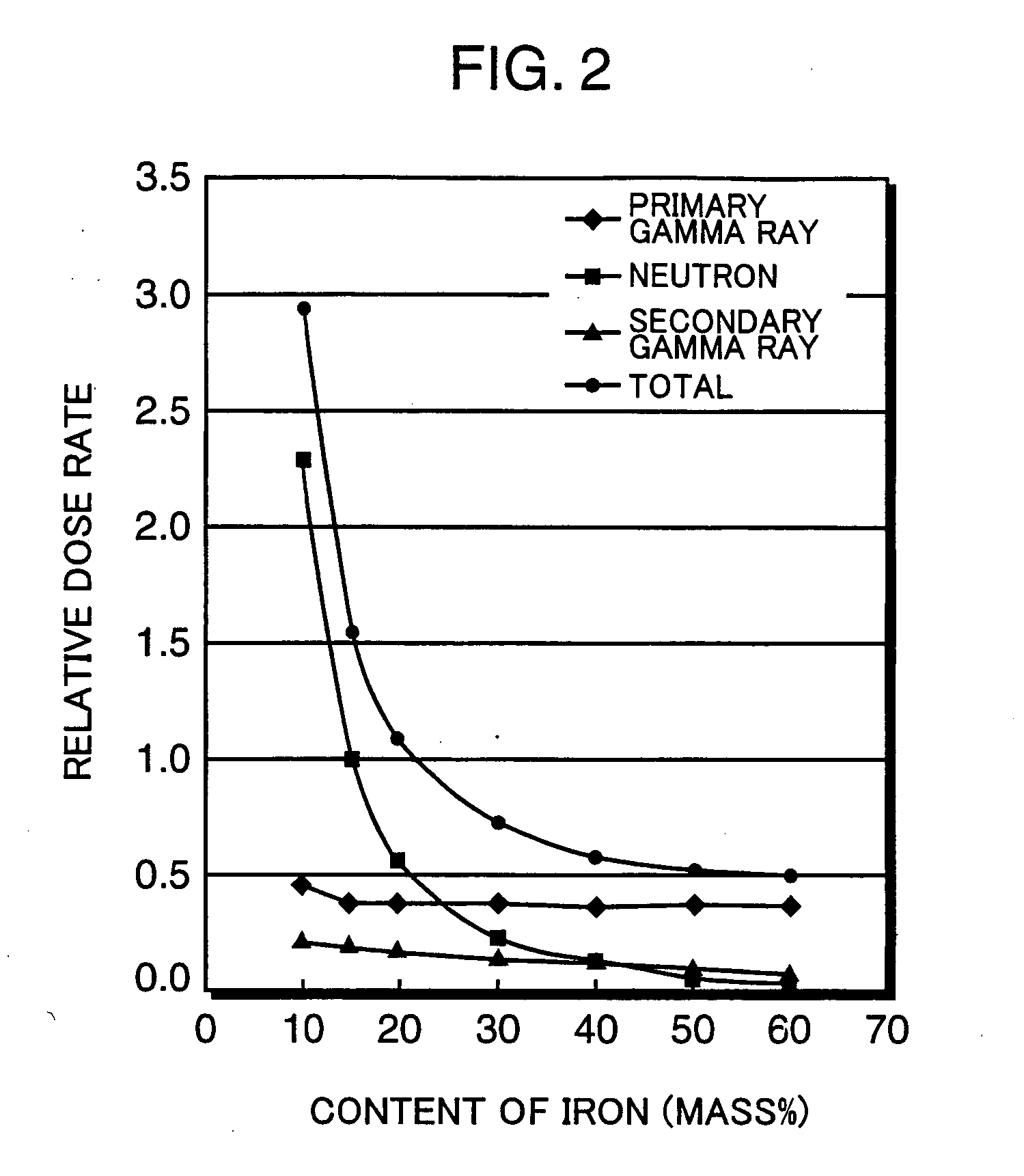
[0043] Assuming composites and concretes produced by blending appropriate quantities of Portland cement, silica fume, calcium hydroxide, chemical admixture and water and adding iron (metallic material) at various ratios, relative dose rates of the concrete cask were calculated on a simulation basis in Experiment 2.

[0044] FIG. 2 shows the relationship between the content of iron and the relative dose rate. In carrying out the simulation, an assumption was made that an iron shield was 17 cm thick, a concrete shield was 41 cm thick, the type of fuel was PWR fuel, burnup was 50,000 MWD / MTU, and cooling time was 10 years.

[0045] It can be seen from FIG. 2 that as the content of iron (metallic material) reaches 10% by mass, the relative dose rate with respect to primary gamma rays becomes lower than 0.6, whereby the concrete of the invention exerts primary gamma ray shielding performance approximately equivalent to or better than that of the ordinary concrete. It can also be seen that the ...

experiment 3

[0046] In this Experiment, composites and concretes were produced by mixing calcium hydroxide and metallic materials (a mixture of iron powder and steel fibers) with Portland cement at various mixing ratios, and the relationship between the proportions of calcium hydroxide and metallic materials in the concrete and its water content at an operating temperature of 150.degree. C. was determined.

[0047] FIG. 3 shows results of this analysis, in which the horizontal axis represents the content of calcium hydroxide and the vertical axis represents the content of the metallic material in terms of mass ratio. If the content of a particular materials is zero, the relevant material is not contained at all. If the content of a particular material is 1, it means that the relevant material has substituted the entirety of cement. Therefore, the sum of the content of calcium hydroxide and the content of the metallic materials does not exceed the value 1 in any case. The water content is expressed ...


PUM

PropertyMeasurementUnit
Fractionaaaaaaaaaa
Fractionaaaaaaaaaa
Fractionaaaaaaaaaa

Abstract

The invention provides a composite from which concrete featuring a sufficiently high heat resistance can be produced, as well as a high-safety sealed concrete cask having no opening (shielding defect) to offer high shielding performance that can prevent corrosion of an internal canister and release of radioactive material to the exterior. A concrete cask of the invention includes a cask body having a bottom but no lid in itself, and a lid which can open and close off a top opening of the cask body. Both the cask body and the lid are made of concrete manufactured by using a composite including Portland cement or blended cement containing Portland cement, which is mixed with water in such a manner that the content of calcium hydroxide falls in a range of 15% to 60% by mass after hardening through hydration reaction. Metallic heat-transfer fins are embedded in the cask body.

Description

[0001] 1. Field of the Invention[0002] The present invention relates to a concrete cask suitable for transportation and long-term storage of radioactive materials, such as spent nuclear fuel. More particularly, the invention is concerned with technology for increasing the performance of the concrete cask through improvements of its cement composite and construction.[0003] 2. Description of the Related Art Conventional technologies concerning concrete casks are disclosed in Japanese Unexamined Patent Publication Nos. 2001-141891 and 2001-305375, for example.[0004] Patent Publication No. 2001-305375 describes an construction of a concrete cask, in which surfaces of the concrete cask are covered by steel plates to prevent its cracking and loss of water content and to achieve enhanced durability, and partitions are provided in the cask to prevent concrete cracking.[0005] Patent Publication No. 2001-141891 describes a concrete cask manufactured by using an ordinary low heat-resistance co...

Claims


Application Information

Patent Timeline
IPC IPC(8): C04B14/02G21C19/06C04B14/34C04B22/00C04B22/06C04B22/08C04B28/02C04B28/04C04B40/02G21F1/04G21F5/005G21F5/008G21F9/36
CPCC04B22/0013C04B22/064C04B28/04C04B2111/00612C04B2111/00862Y10T428/131G21F1/042G21F1/047G21F5/005C04B2111/00948C04B14/34C04B40/0263C04B2103/0088C04B14/48G21F9/36
Inventor TANIUCHI, HIROAKISHIMOJO, JUNSUGIHARA, YUTAKAOWAKI, EIJIOKAMOTO, REIKO
Owner KOBE STEEL LTD
Learn More