Biosensor

a biosensor and sensor technology, applied in the field of biosensors, can solve the problems of destroying the hemocytes captured in the filter to dissolve hemoglobin, making it impossible to measure whole blood as done in the glucose sensor, and affecting the measurement accuracy of the glucose sensor, so as to eliminate the possibility of destroying the hemocytes and the effect of rapid flow into the sensor

Inactive Publication Date: 2004-05-20
PANASONIC CORP
View PDF3 Cites 24 Cited by
  • Summary
  • Abstract
  • Description
  • Claims
  • Application Information

AI Technical Summary

Benefits of technology

0068] In general, the reaction layer is easy to dissolve in one portion and hard to dissolve in other portion. The easy-to-dissolve portion lies along the edge of the sample solution supply part 12', i.e., along the wall surface of the slit 12 of the spacer 7. The hard-to-dissolve portion is a center portion of the reaction layer in the liquid flow direction. Since the sample solution having passed the filter 6 flows along the slit 12 by priority, the sample solution may fill the air aperture in some cases before the center portion of the reaction layer dissolves completely. With the secondary side portion of the filter 6 shaped such that a center thereof is projected inside of the sample solution supply pathway 12' as compared with the right and left, the sample solution flows along the center portion of the sample solution supply pathway 12' by priority. Thereby, the plasma can rapidly be flown into the sensor without leaving bubbles in the center portion of the sample solution supply pathway 12'.
0069] In measurement, a fingertip stung to bleed is placed on the sample solution supply part 30 to supply blood to the filter 6. The blood permeates into the filter 6 from the end face and the top face on the primary side. At this time, with the existence of the third pressing part c serving as a partition, the blood does not travel on the surface of the filter 6 by priority to flow directly into the sample solution supply pathway 12'. Further, since the third and first pressing parts c and a do not agree in position as viewed in a projection on a plane identical to the insulating base plate 1, the expansion of the filter 6 is not inhibited and the possibility of destroying the hemocytes is eliminated.

Problems solved by technology

However, the surfactant included in the reaction system affects adversely on hemocytes, which makes impossible to measure whole blood as done in the glucose sensor.
However, if the filter is inappropriately built in the sensor, hemocytes captured in the filter are destroyed to dissolve hemoglobin out.
Thereby, filtration of the hemocyte components with the filter becomes difficult and small hemoglobin flows into the sample solution supply pathway to cause a measurement error.
As opposed to this, if the gap between the upper and lower pressing parts is previously set wide for the supposed thickness of the expanded filter taking into account that the degree of the filter expansion varies depending on a hematocrit value (volume percent of red cell) different in each sample solution, it is feared that the filter may be misaligned during storage of the sensor.
Then, the rate at which the plasma flows out of a secondary side of the filter is reduced and the rate at which the plasma saturates the inside of the sensor, in particular the inside of the sample solution supply pathway, becomes low, which results in long measurement time.
The sample solution having flown along the filter surface then flows into the sample solution supply pathway from an opening thereof connecting the sample solution supply pathway and the filter, which may cause a measurement error.
However, if the sensor is improved in suction power to achieve challenges of reducing the sample solution and the measurement time and the sample solution is dropped directly onto the filter, the hemocytes often flow into the sample solution supply pathway from the opening thereof connecting the sample solution supply pathway and the filter even in the presence of the third pressing part for holding the center of the filter from the top.
Further, in a sensor described in the specification of Japanese Patent Application No. 2000-399056 in which the sample solution is sucked from an end face of the filter or a sensor described in the specification of Japanese Patent Application No. 2001-152868 in which the sample solution is sucked from a top face of the filter, it has been difficult to rub or drop whole blood on a fingertip against or onto the sensor with efficiency.
Therefore, these sensors have not been adapted to the measurement involving blood collection by fingertip centesis.

Method used


Image

  • Biosensor
  • Biosensor
  • Biosensor

Examples


Embodiment Construction

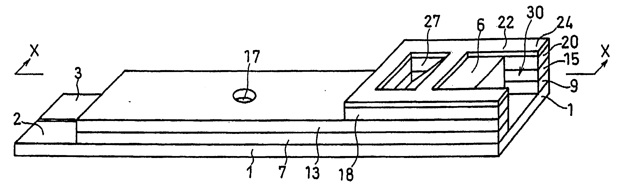
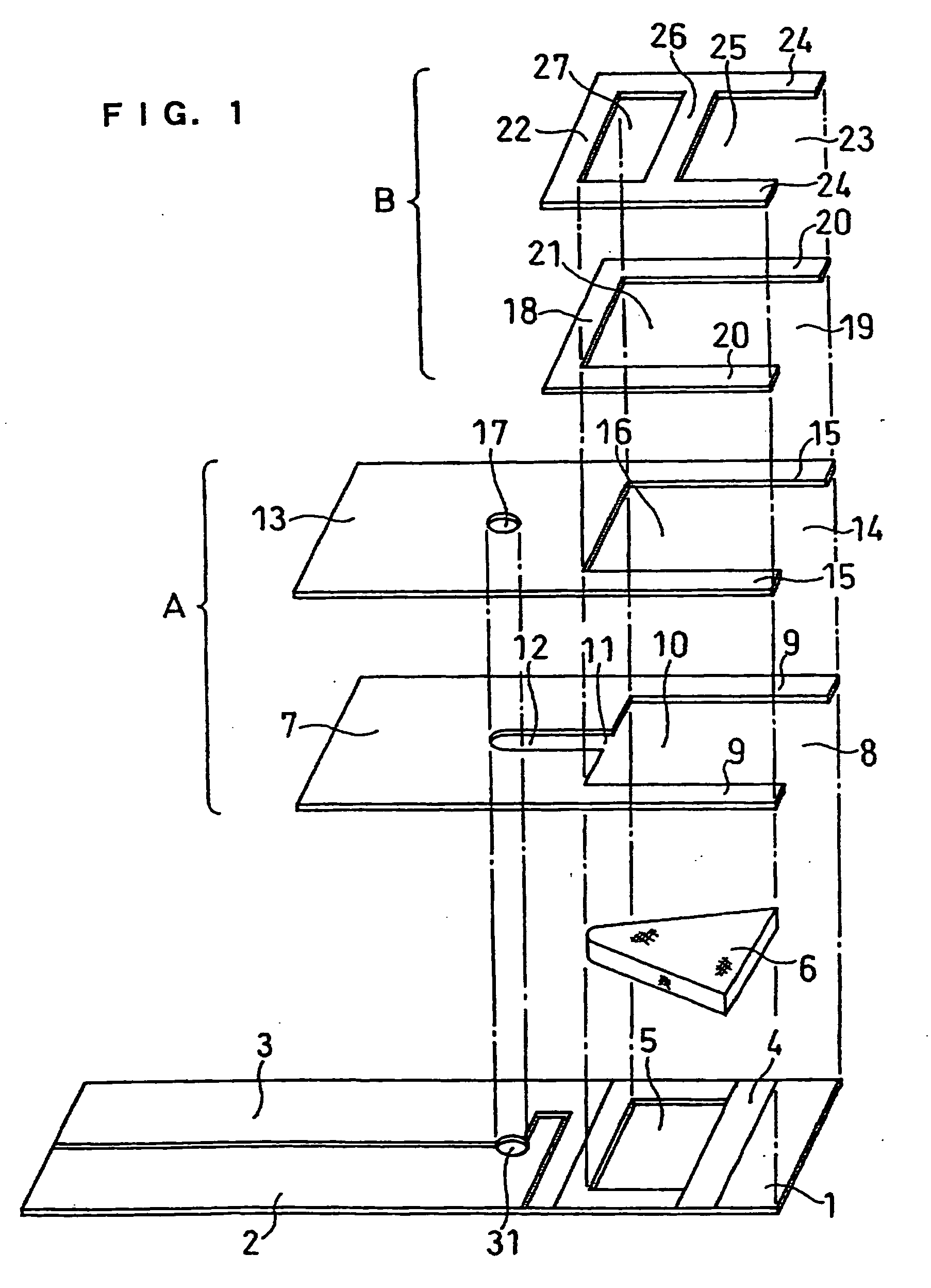
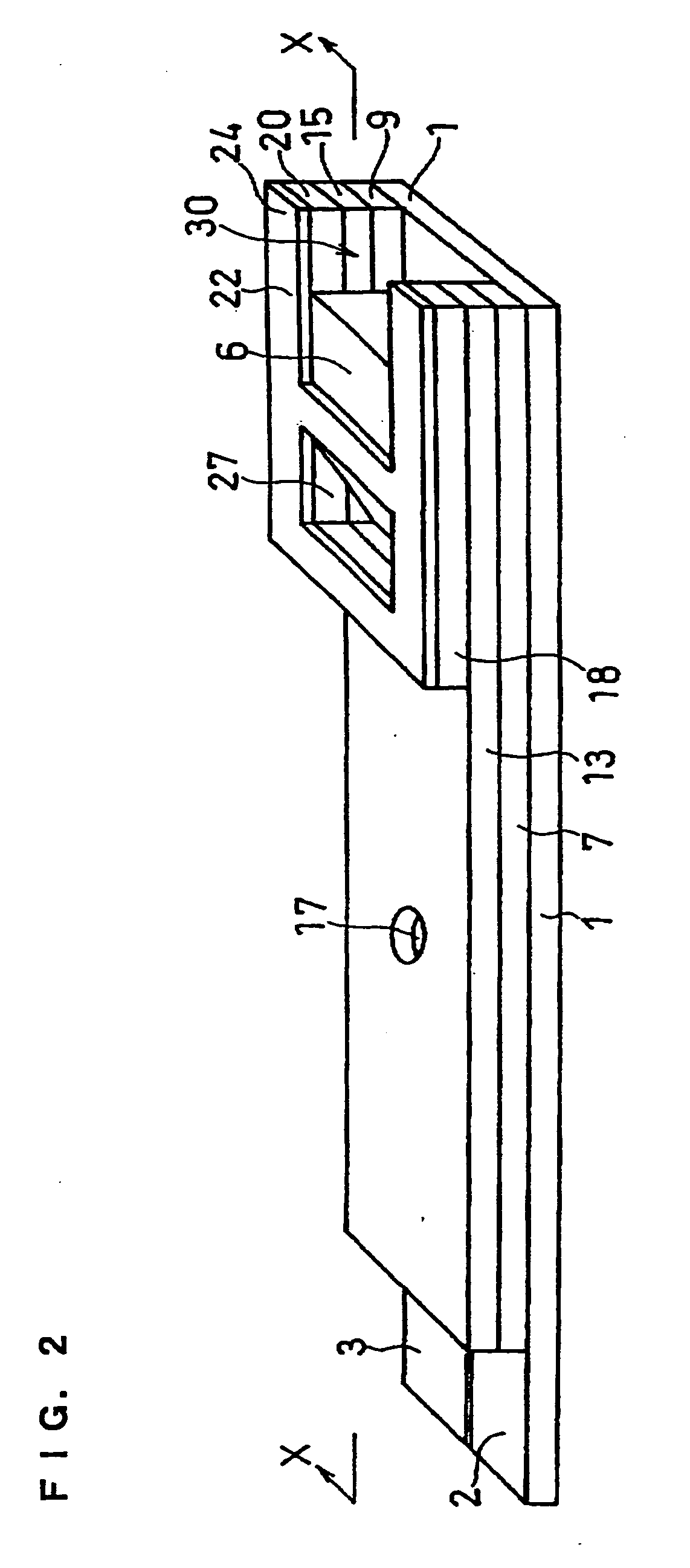
[0072] A cholesterol sensor configured as shown in FIGS. 1, 2 and 4 was fabricated in the following manner. An electron mediator was contained in a reaction layer 29 and cholesterol oxidase, cholesterol esterase and a surfactant were contained in a reaction layer 29'.

[0073] First, 5 .mu.l of 0.5 wt % CMC aqueous solution was dropped onto the electrode system of the insulating base plate 1 and dried in a warm-air dryer at 50.degree. C. for 10 minutes to form a hydrophilic polymer layer 28.

[0074] Then, 4 .mu.l of potassium ferricyanide aqueous solution (corresponding to 70 mM of potassium ferricyanide) was dropped onto the hydrophilic polymer layer 28 and dried in the warm-air drier at 50.degree. C. for 10 minutes to form a reaction layer 29 containing potassium ferricyanide. Further, to a solution dissolved therein cholesterol oxidase derived from Nocardia (EC1.1.3.6: ChOD) and cholesterol esterase derived from Pseudomonas (EC.3.1.1.13: ChE), polyoxyethylene (10) octyl phenyl ether (...


PUM

PropertyMeasurementUnit
pore diameteraaaaaaaaaa
thicknessaaaaaaaaaa
thicknessaaaaaaaaaa

Abstract

In a biosensor comprising an insulating base plate, an electrode system including a measuring electrode and a counter electrode provided on said base plate, a cover for covering said insulating base plate, at least one reaction layer containing oxidoreductase and/or an electron mediator, a sample solution supply pathway including said electrode system and said reaction layer and communicating with an air aperture at a terminal end side, a sample solution supply part and a filter provided between said sample solution supply pathway and said sample solution supply part to filter hemocytes, an end face and a top face of a primary portion of the filter are exposed and the sample solution supply part is provided adjacently to the primary side portion so as to provide an improved biosensor which allows easy addition of whole blood to the sensor and rapid supply of the added whole blood to a filter even in the case of collecting blood by fingertip centesis for measurement.

Description

[0001] The present invention relates to a biosensor, specifically a cholesterol sensor, capable of determining the quantity of a specific component in a sample in a speedy, highly-sensitive and simple manner.[0002] A description is given to an example of a conventional biosensor in terms of a glucose sensor.[0003] A typical glucose sensor is obtained by forming an electrode system including at least a measuring electrode and a counter electrode on an insulating base plate by screen printing or the like and forming an enzyme reaction layer containing a hydrophilic polymer, oxidoreductase and an electron mediator on the electrode system. For example, glucose oxidase is used as oxidoreductase and a metal complex or an organic compound such as potassium ferricyanide, ferrocene derivatives and quinone derivatives is used as the electron mediator. A buffer is added to the enzyme reaction layer if required.[0004] Upon dropping a sample solution containing a substrate onto the enzyme reacti...

Claims


Application Information

Patent Timeline
Patent Type & Authority Applications(United States)
IPC IPC(8): C12Q1/00G01N33/49
CPCC12Q1/001G01N33/491G01N27/3272
Inventor HASEGAWA, MIWAYAMAMOTO, TOMOHIROIKEDA, SHINYOSHIOKA, TOSHIHIKO
Owner PANASONIC CORP
Why Eureka
Try Eureka