Coated and magnetic particles and applications thereof

a technology of magnetic particles and coatings, applied in the field of magnetic or non-magnetic particles, can solve the problems of high cost of ownership, severe limitations on bump height, and inconvenient use of solder materials

Inactive Publication Date: 2004-06-17
SURFECT TECH
View PDF85 Cites 68 Cited by
  • Summary
  • Abstract
  • Description
  • Claims
  • Application Information

AI Technical Summary

Benefits of technology

0041] FIGS. 2A-B depict the effect of particle loading on bump shape;

Problems solved by technology

Evaporation methods require substantial investment in capital equipment and typically entail high cost of ownership.
Electroplating methods are known to drive the trend for finer bump pitch, but some solder materials are not suitable because of electroplating bath constraints.
Screen printing methods typically are the most cost efficient; but there can be severe limitations on bump height when the bump pitch is less than 200 microns.
However, these approaches require multiple processing steps, increasing the complexity and cost.
In addition, solder pastes have been blended from elemental powders, but these have the disadvantages of poor shelf life, stratification in the paste (which greatly reduces uniformity and thus reliability), and the use of organic binders which are incompatible with some applications.
The time involved in this process is not conducive to chemical or cost-effective processing.
The features that result require a very complicated seed metallization to provide the current buss flow to carry out the electrodeposition.
This process requires a complicated plasma vapor deposition of a seed metal layer.
This seed metal layer becomes very complicated to accomplish when the aspect ratio of the via feature exceeds 10 to 1.
The current practice is to use more complicated methods of cross-sputtering and still the resulting result is not sufficient to assure a high-quality and cost-effective process.
Quantitative analysis of these results is complicated by lack of adequate knowledge of the microstructure of the magnetically modified catalyst layer, but it is estimated that only about 25% of the catalyst is active when CO is present.
This approach has been limited to the use of relatively weak magnetic particles, because attempts to form catalyst layers from particles of higher magnetic strength failed to yield smooth, physically stable layers.
High field-strength particles pose undesirable force affecting the electrodes integrity by fracturing and deforming bed-layer compact.
Introduction of magnetic particles in the ink introduces new complications, such as how to apply and stabilize a thin layer while magnetic forces attract the particles together, during application and after drying of the applied ink.
's method has other disadvantages, including segregation of each constituent resulting in non-uniformity of the final product and complex manufacturing process.

Method used


Image

  • Coated and magnetic particles and applications thereof
  • Coated and magnetic particles and applications thereof
  • Coated and magnetic particles and applications thereof

Examples


example

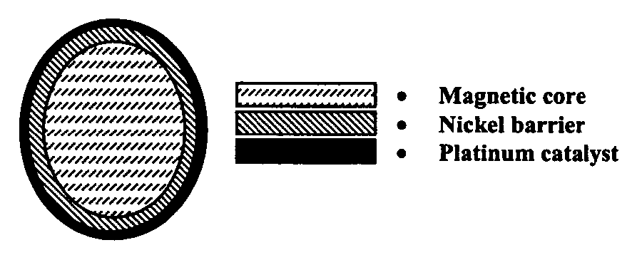
[0062] Magnetic Core Catalyst Particles

[0063] An example of the use of coated magnetic core powders is in the manufacture of electrocatalyst materials for applications including, but not limited to, fuel cells. Not only does the use of magnetic core powders improve manufacturability of the device, it enhances its efficiency as well. The present invention comprises coating a magnetic particle, preferably Ni, with a catalytic material, preferably a metal, and preferably platinum. Optionally, other elements such as ruthenium may be added to the surface, either entirely encapsulating the particle or partially coating the surface, to tailor the catalyst's mechanical, electrochemical, electronic, and / or magnetic properties. The partial coatings may comprise isolated islands of the additional element. The ruthenium may optionally be oxidized.

[0064] The use of a magnetic material in catalyst electrodes results in improved catalytic properties. The magnetic moment of the core particles impro...


PUM

PropertyMeasurementUnit
heightaaaaaaaaaa
heightaaaaaaaaaa
heightaaaaaaaaaa

Abstract

A method of using coated and/or magnetic particles to deposit structures including solder joints, bumps, vias, bond rings, and the like. The particles may be coated with a solderable material. For solder joints, after reflow the solder material may comprise unmelted particles in a matrix, thereby increasing the strength of the joint and decreasing the pitch of an array of joints. The particle and coating may form a higher melting point alloy, permitting multiple subsequent reflow steps. The particles and/or the coating may be magnetic. External magnetic fields may be applied during deposition to precisely control the particle loading and deposition location. Elements with incompatible electropotentials may thereby be electrodeposited in a single step. Using such fields permits the fill of high aspect ratio structures such as vias without requiring complete seed metallization of the structure. Also, a catalyst consisting of a magnetic particle coated with a catalytic material, optionally including an intermediate layer.

Description

[0001] This application claims the benefit of the filing of U.S. Provisional Patent Application Serial No. 60 / 431,315, entitled "Solid core solder particles for printable solder paste", filed on Dec. 5, 2002, U.S. Provisional Patent Application Serial No. 60 / 447,175, entitled "Electrochemical Devices and Processes", filed on Feb. 12, 2003, and U.S. Provisional Patent Application Serial No. 60 / 519,813, entitled "Particle Coelectrodeposition", filed on Nov. 12, 2003. This application is a continuation-in-part of U.S. patent application Ser. No. 09 / 872,214, entitled "Submicron and Nanosize Particle Encapsulation by Electrochemical Process and Apparatus", filed May 31, 2001. The specifications of each application listed are incorporated herein by reference.[0002] 1. Field of the Invention (Technical Field)[0003] The present invention relates to magnetic or nonmagnetic particles which are coated with a desired material before the particles are deposited on a substrate or surface. The coa...

Claims


Application Information

Patent Timeline
Patent Type & Authority Applications(United States)
IPC IPC(8): B23K35/02C25D7/12C25D17/16H01F41/16H01F41/20H01F41/26H01L21/288H01L21/60H01L21/768H01L23/485H05K3/34
CPCB22F2998/00Y10T428/12063H01F41/16H01F41/20H01F41/26H01L21/2885H01L21/76877H01L21/76898H01L24/11H01L24/12H01L2224/1132H01L2224/1147H01L2224/13009H01L2224/13099H01L2224/16H01L2924/01013H01L2924/01027H01L2924/01029H01L2924/01046H01L2924/01047H01L2924/01056H01L2924/0106H01L2924/01078H01L2924/01079H01L2924/01082H01L2924/01322H01L2924/01327H01L2924/09701H01L2924/1433H01L2924/19041H01L2924/19042H01L2924/19043H01L2924/30107H05K3/3473H05K3/3484H05K2201/0215H05K2201/0218H05K2201/083H05K2203/0425H05K2203/043H05K2203/104B23K35/0244C25D7/123H05K2201/09572H01L2924/01012H01L2924/014H01L2924/01044C25D15/00C25D15/02B22F2999/00H01L2224/11334H01L2924/01005H01L2924/01006H01L2924/01033B22F1/025B22F1/0088H01L2924/15787H01L2224/05571H01L2224/05573H01L2224/05568H01L2924/00014H01L24/13H05K3/3485H01L2924/00H01L2224/05599B22F1/17B22F1/145
Inventor GRIEGO, THOMAS P.
Owner SURFECT TECH
Why Eureka
Try Eureka