
Optical compensatory sheet comprising transparent support and optically anisotropic layer

a technology of optical anisotropy and transparent support, which is applied in the direction of instruments, transportation and packaging, chemistry apparatus and processes, etc., can solve the problems of discotic liquid crystal molecules that are optically uniaxial in principle, and it is difficult to obtain optical characteristics of optically biaxial polymer films

Inactive Publication Date: 2004-08-05
FUJIFILM CORP
View PDF14 Cites 24 Cited by
  • Summary
  • Abstract
  • Description
  • Claims
  • Application Information

AI Technical Summary

Benefits of technology

[0021] Further, an optical compensatory sheet can be prepared with very high productivity. A rubbing treatment of an orientation layer can be easily conducted along a longitudinal direction of a rolled transparent support. If the slow axis in plane of an optically anisotropic layer is parallel to the width of the optical compensatory sheet in the form of a roll, the rolled optical compensatory sheet and a rolled polarizing membrane can be continuously laminated (so that the slow axis may be parallel to the transmitting axis of the polarizing membrane). In other words, the rubbing treatment of the orientation layer can be conducted along a longitudinal direction (i.e., along the easiest direction) to form the slow axis in the plane of the optically anisotropic layer along the width, whereby the optical compensatory sheet and the polarizing membrane can be easily laminated. Consequently, an optical compensatory sheet can be prepared with very high productivity by using optically biaxial liquid crystal molecules, which can form an optically anisotropic layer in which the slow axis in plane is essentially perpendicular to the rubbing direction of the orientation layer.
[0035] The transparent support can be subjected to a surface treatment (e.g., alkaline treatment, acid treatment, glow discharge treatment, corona discharge treatment, ultraviolet (UV) treatment, flame treatment) to improve adhesion to a layer formed on the support (e.g., adhesive layer, orientation layer, optically anisotropic layer). An adhesive layer (undercoating layer) can be also provided on the transparent support.
[0045] After the liquid crystal molecules are aligned with the orientation layer, the aligned liquid crystal molecules are fixed with the alignment maintained to form an optically anisotropic layer. The optically anisotropic layer can be transferred onto the transparent support. The aligned and fixed liquid crystal molecules can keep the alignment without the orientation layer.

Problems solved by technology

However, rod-like or discotic liquid crystal molecules are optically uniaxial in principle.
Accordingly, it is technically difficult to obtain optical characteristics of the optically biaxial polymer film by using an optically anisotropic layer formed from rod-like or discotic liquid crystal molecules.

Method used


Image

  • Optical compensatory sheet comprising transparent support and optically anisotropic layer
  • Optical compensatory sheet comprising transparent support and optically anisotropic layer
  • Optical compensatory sheet comprising transparent support and optically anisotropic layer

Examples


example 2

[0156] Polyvinyl alcohol (PVA-203, Kuraray Co., Ltd.) was dissolved in a mixed solution of methanol and water (volume ratio: 20 / 80) to prepare 5 wt. % solution. The solution was applied on a glass plate by means of a bar coater, and dried by air at 80.degree. C. for 10 minutes.

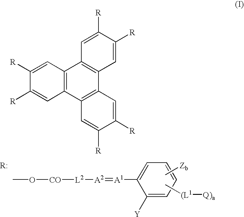
[0157] To 1.0 g of discotic liquid crystal molecules (I-2), 10 mg of the following additive and 30 mg of the following photo polymerization initiator were mixed. The mixture was then dissolved in methyl ethyl ketone to prepare 20 wt. % solution, and the solution was applied on the polyvinyl alcohol layer by means of a bar coater. 57

[0158] The naked surface (bottom surface) of the glass substrate was made to be in contact with a heated metal roller (a surface temperature: 130.degree. C.) for 2 minutes, and then further made to be in contact with a slightly heated metal roller (a surface temperature: 30.degree. C.) for 1 minute. The coated surface was exposed to non-polarized ultraviolet light from a 160 W ultra...

example 3

[0161] A glass plate was coated with polyimide (SE-150, Nissan Chemicals, Co., Ltd.), and dried at 210.degree. C. for 60 minutes. The surface was then subjected to rubbing treatment along a certain direction, to form an orientation layer.

[0162] 3.0 g of rod-like liquid crystal molecules (II-11), 500 mg of a polymerization initiator (Irgacure 369, Ciba-Geigy) and 3 mg of a chiral agent (S811, Merck) were dissolved in 10 ml of N-methylpyrrolidone. The solution was dropped on the orientation layer, and then spin-coated (rotation: 1,000 rpm). After the solvent was evaporated by heating at 100.degree. C. for 30 minutes, the surface was observed by a polarizing microscope to find that the rod-like liquid crystal molecules were oriented in cholesteric alignment.

[0163] The surface was then exposed to non-polarized ultraviolet light from a 160 W ultraviolet ray irradiating apparatus (UVL-58, ULTRA-VIOLET-PRODUCT) for 10 seconds, to fix the alignment of the rod-like liquid crystal molecules.

[...


PUM

PropertyMeasurementUnit
Lengthaaaaaaaaaa
Angleaaaaaaaaaa
Lengthaaaaaaaaaa

Abstract

An optical compensatory sheet comprises a transparent support and an optically anisotropic layer. The optically anisotropic layer is formed from liquid crystal molecules. Three principal refractive indices of the optically anisotropic layer are different from each other.

Description

[0001] The present invention relates to an optical compensatory sheet which comprises a transparent support and an optically anisotropic layer formed from liquid crystal molecules.[0002] A liquid crystal display generally comprises a liquid crystal cell, a polarizing element and an optical compensatory sheet (phase retarder). In a display of transmission type, two polarizing elements are provided on both sides of the liquid crystal cell, and one or two optical compensatory sheets are placed between the liquid crystal cell and the polarizing element. A display of reflection type comprises a reflection plate, a liquid crystal cell, an optical compensatory sheet and a polarizing element in this order.[0003] The liquid crystal cell comprises a pair of substrates, rod-like liquid crystal molecules and an electrode layer. The rod-like liquid crystal molecules are provided between the substrates. The electrode layer has a function of applying a voltage to the rod-like liquid crystal molecu...

Claims


Application Information

Patent Timeline
IPC IPC(8): C09K19/16C09K19/20C09K19/22C09K19/24C09K19/32C09K19/38
CPCC09K19/16C09K19/2014C09K19/22C09K19/24C09K19/32Y10T428/1036C09K2019/328Y10T428/1005Y10T428/1059Y10T428/10C09K19/3852C09K2323/00C09K2323/02C09K2323/03C09K2323/05
Inventor AMINAKA, EIICHIRONISHIKAWA, HIDEYUKIKAWATA, KEN
Owner FUJIFILM CORP
Learn More