
Energy distribution network

a technology of energy distribution network and energy input, applied in the direction of energy input, electric/hybrid propulsion, process and machine control, etc., can solve the problems of global and regional conflict, essentially impossible to achieve, and uncertainty about the impact of greenhouse gas emissions on health and climate chang

Inactive Publication Date: 2004-10-07
FAIRLIE MATTHEW J +4
View PDF67 Cites 36 Cited by
  • Summary
  • Abstract
  • Description
  • Claims
  • Application Information

AI Technical Summary

Benefits of technology

This network enables better asset utilization, reduces environmental impact, and optimizes energy distribution by providing real-time data for decision-making, allowing for more efficient hydrogen production and storage, thus addressing the limitations of existing hydrocarbon fuel systems.

Problems solved by technology

Many believe to put a widespread, geographic network of hydrogen vehicles with a network of hydrogen supply encompassing production, storage, transportation and delivery would involve such a large investment and be so challenging, that the task is believed essentially impossible to do in any economic method.
In fact, much of the world's hydrocarbon resources are focused in just a few geographical areas, such that many nations do not have a substantive supply of indigenous fuel.
This has led to global and regional conflict.
In addition, there is uncertainty about the impact of greenhouse gas emissions on health and climate change.
Furthermore, the very use of hydrocarbon fuels, or the processing for use of hydrocarbon fuels, leads to ground level pollution of smog and ozone as well as regional environmental challenges, such as acid rain.
Airborne pollutants, either directly or indirectly formed due to the combustion or processing of hydrocarbon fuels, lead to reduced crop output, potentially reduced lifespan and other health issues for all living beings.
It can, thus, be seen that the decisions concerning a chemical plant for, say, methanol production which then is used for many applications including on-board or off-board reforming of methanol can not provide instantaneous and daily information to influence production decisions.
Once electricity is produced, it is difficult to store effectively and must be transmitted through some form of distribution / transmission system.

Method used


Image

  • Energy distribution network
  • Energy distribution network
  • Energy distribution network

Examples


Embodiment Construction

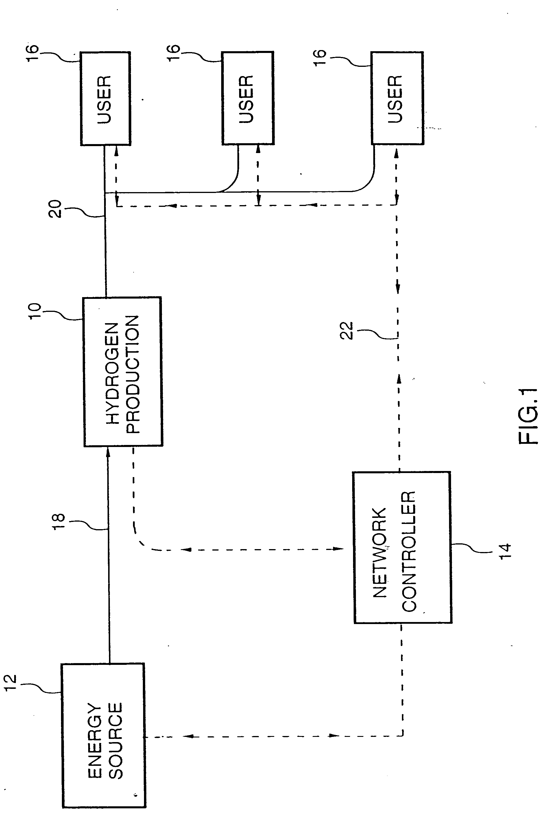
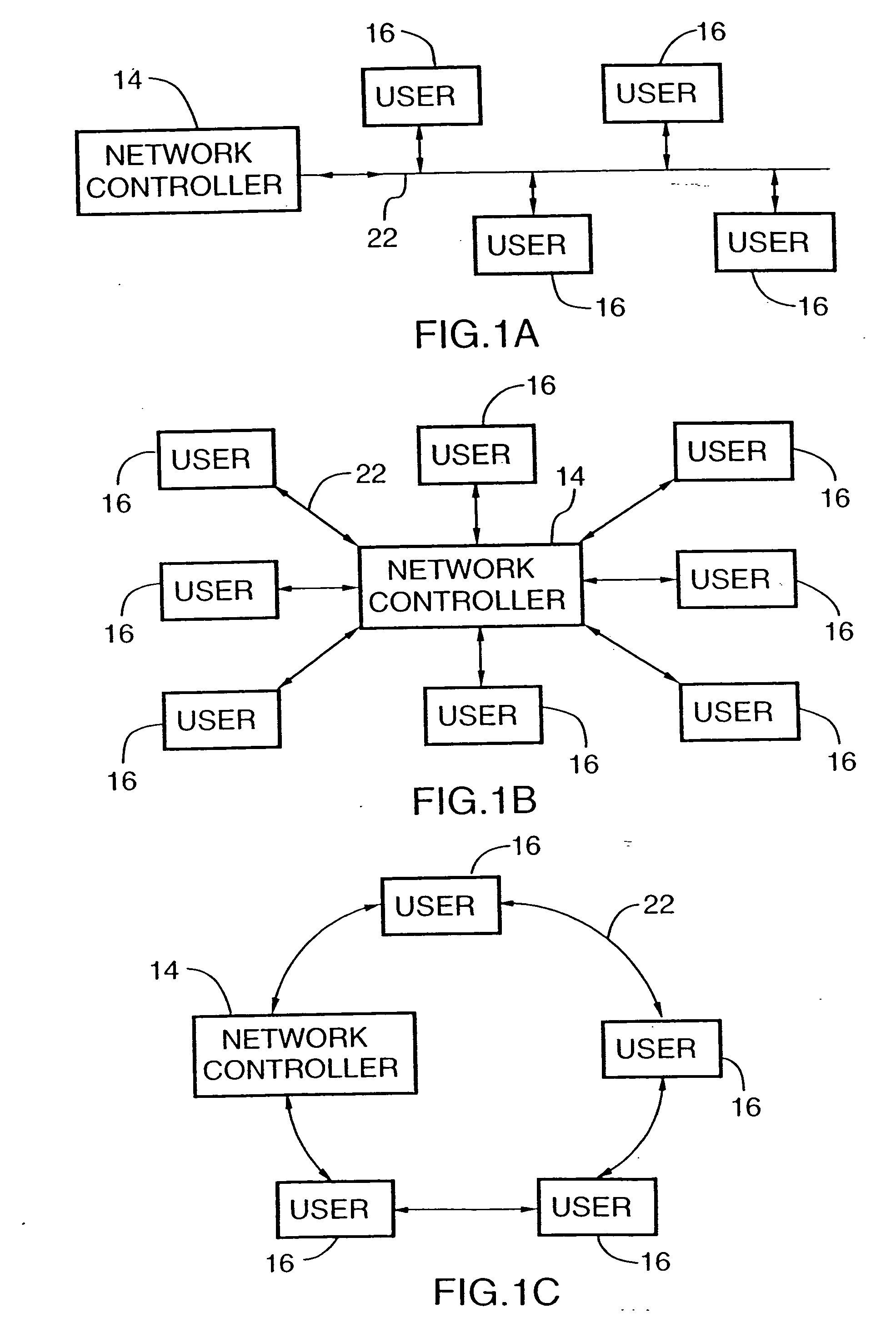
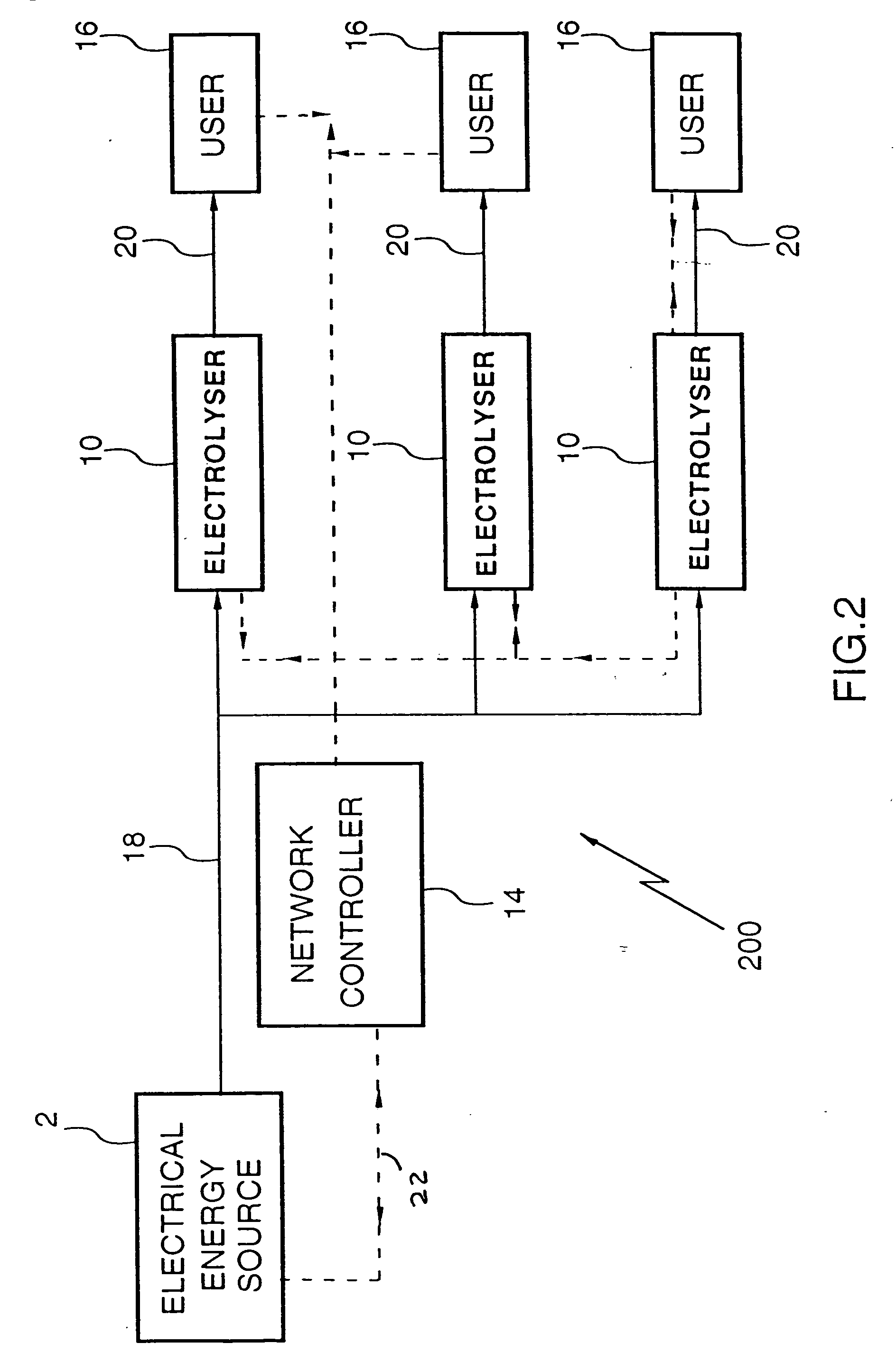
[0071] FIG. 1 represents an embodiment providing a broad aspect of the invention having a hydrogen production source 10, supplied by energy source 12 which may be an electricity generating power plant, or a natural gas, gasoline or methanol reforming plant or combinations thereof. A control unit 14 and users 16 are suitably linked by hardware input and output distribution conduits 18, 20, respectively, and electrical data transmission lines 22.

[0072] Users 16 define demands for hydrogen transmitted by means of, for example (i) use of a credit card, (ii) use of a smart card, (iii) use of a voice activation system, (iv) manual activation via front panel control, (v) use of a electronic, electric, or wireless infrared data transmission system to register a hydrogen demand on the network. Upon receipt of the demand, controller 14 determines the natures of the demand with respect to the quantity of hydrogen requested, the time to deliver the hydrogen, the conditions under which to delive...


PUM

PropertyMeasurementUnit
electrical energyaaaaaaaaaa
currentaaaaaaaaaa
temperature/pressureaaaaaaaaaa

Abstract

A hydrogen fuel supply system includes a hydrogen generator for generating hydrogen from an energy source at an outlet pressure. An outlet conduit feeds the hydrogen to a user. A controller controls the hydrogen generator to produce hydrogen at the outlet pressure. An input interface receives user demand data and activates the controller in accordance with the user demand data.

Description

[0001] This invention relates to an energy network for providing hydrogen generated at a production site, particularly by one or more water electrolysers, for use particularly, as a fuel for vehicles or energy storage. The invention further relates to the use of hydrogen as a fuel for a fuel cell wherein hydrogen is converted into electrical energy, for combustion as an auxiliary energy source and for the generation of electricity, particularly, as part of an electrical distribution system.BACKGROUND TO THE INVENTION[0002] In planning the production capacity of a large chemical plant, for example, for methanol production or a large electricity production site, correct knowledge of expected demand of the product is critical with regard to the optimization of capital deployment and certainty of a return on investment in the large facility. Most often millions of dollars are required to finance the construction. Thus, measuring and predicting the supply and demand for the end product i...

Claims


Application Information

Patent Timeline
Patent Type & Authority Applications(United States)
IPC IPC(8): B60L11/18C25B15/02C01B3/00C25B1/04H01M8/0656
CPCB60L11/1881B60L2200/26B60L2260/54B60L2260/56C01B3/00C01B3/02C01B3/32C01B3/36C01B2203/0233C01B2203/025C01B2203/1223C01B2203/1235C01B2203/1241C01B2203/84H01M8/04216H01M8/04298H01M8/0438H01M8/04753H01M8/0612H01M8/0656H01M2250/20H01M2250/402Y02B90/12Y02E60/324Y02E60/366Y02T90/32Y02T90/34Y02E60/50B60L11/1894Y02P20/133B60L58/30B60L58/34Y02B90/10Y02E60/32Y02E60/36Y02T90/40Y02P90/60
Inventor FAIRLIE, MATTHEW J.STEWART, WILLIAM J.STUART, ANDREW T. B.THORPEDONG, CHARLIE
Owner FAIRLIE MATTHEW J
Learn More