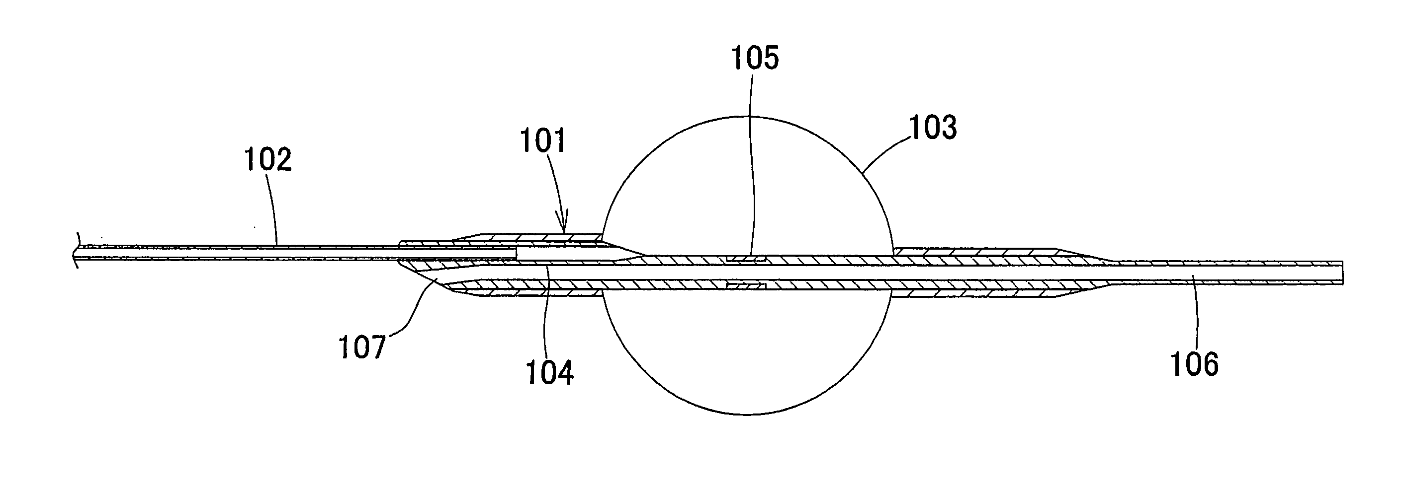
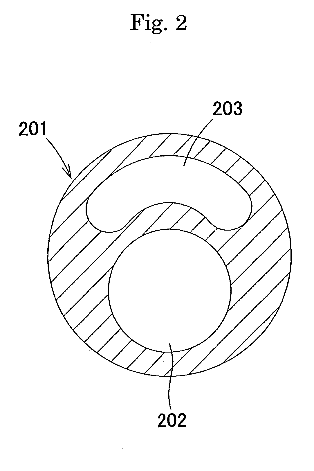
Balloon catheter for tentative vaso-occlusion

a balloon catheter and vaso-occlusion technology, applied in balloon catheters, surgery, angiography, etc., can solve the problems of slow flow or no flow phenomenon, occlusion of downstream peripheral blood vessels, and recovery time, and achieve the effect of superior maneuverability

Inactive Publication Date: 2004-12-30
KANEKA CORP
View PDF5 Cites 27 Cited by
  • Summary
  • Abstract
  • Description
  • Claims
  • Application Information

AI Technical Summary

Benefits of technology

0011] The present invention aims to provide a temporary occlusion balloon catheter that can itself function as a guidewire, that has superior maneuverability suitable for highly tortuous or branche...

Problems solved by technology

When the blood vessel occlusion is caused by thrombi, expansion of the occluded area with a balloon catheter may cause the thrombi to detach from the inner wall of the blood vessels, thereby causing occlusion of downstream peripheral blood vessels.
This results in a slow-flow or no-reflow phenomenon.
However, the recovery requires time.
However, this also requires time before the recovery of the blood flow can be achieved.
Ischemia can kill brain cells if it continues for a long period of time, and severe and permanent damage may result.
However, the balloon of a catheter of this type is located approximately 30 mm from the distal end of the guidewire, and the stiffness of the guidewire is insufficient due to the hollow catheter shaft.
Accordingly, the guidewire has low maneuverability and cannot be used in highly tortuous and branched blood vessels such as coronary and cerebral arteries.
Moreover, conventional intravascular temporary occlusion balloon catheters do...

Method used


Image

  • Balloon catheter for tentative vaso-occlusion
  • Balloon catheter for tentative vaso-occlusion
  • Balloon catheter for tentative vaso-occlusion

Examples


example 2

[0049] FIG. 3 shows another example of the present invention. The structure of a catheter 301 is basically the same as in EXAMPLE 1. In FIG. 3, reference numeral 302 denotes a shaft, 303 denotes a balloon, 304 denotes a base shaft, 305 denotes a radiopaque marker, 306 denotes a guidewire lumen, and 307 denotes a guidewire port. The difference from EXAMPLE 1 lies in that the balloon was composed of thermoplastic polyurethane Tecoflex EG85A manufactured by Thermedics, that methylene chloride was used as the solvent, and that a high-density polyethylene thin tube was used as the guidewire lumen tube for making the guidewire lumen. The guidewire lumen tube had a 1-mm projected portion at the guidewire port portion and this portion was crushed. FIG. 4 is a diagram viewed from the A-A cross-section of FIG. 3 in the direction toward the catheter distal end. In FIG. 4, reference numeral 401 denotes a base shaft, 402 denotes a shaft cross-section, 403 denotes a guidewire port, and 404 denote...

example 3

[0050] In EXAMPLE 3, the guidewire lumen for tracking the guidewire was formed at the distal-end side of the balloon. FIG. 5 shows the structure of this example. A shaft 502 of a catheter 501 was a metal tube composed of SUS 304 stainless steel having the same dimensions as in EXAMPLE 1. A SUS 304 stainless steel core wire 508 having a proximal-side outer diameter of 0.2 mm and a length of 18 mm was disposed at the distal-end portion of the shaft 502. The reason for providing this core wire 508 is to gradually change the stiffness from the shaft 502 to the catheter distal-end portion so that a guidewire lumen 506 is formed at the distal-end portion of the shaft 502. The core wire 508 may be tapered so that the wire becomes gradually thinner toward the distal end. In this manner, the stiffness of the catheter distal-end portion can gradually decrease. In this example, the core wire 508 was adjusted so that the outer diameter at the most distal end was 0.15 mm. Although YAG laser proc...

example 4

[0051] FIG. 6 shows another example of the present invention. The structure of a catheter 601 is basically the same as in EXAMPLE 1. The difference from EXAMPLE 1 lies in that a shaft 602 is constituted from a distal-end shaft 607 composed of a NiTi alloy, i.e., a superelastic metal, and a proximal-end shaft 609 composed of SUS 316 stainless steel. The superelastic metal tube (the distal-end shaft 607) had a length of 400 mm, an outer diameter of 0.35 mm, and an inner diameter of 0.28 mm. The distal-end shaft 607 was bonded to the proximal-end shaft 609 via an extension tube 608 using a two-part urethane adhesive, as shown in FIG. 6. The extension tube 608 had a length of 20 mm, an outer diameter of 0.25 mm, and an inner diameter of 0.18 mm and was composed of SUS 316 stainless steel. In bonding the extension tube 608 to these shafts, appropriate care must be taken to prevent the adhesive from flowing into the lumens of the shafts. In order to avoid the formation of a step differenc...


PUM


Abstract

The present invention aims to provide an intravascular temporary occlusion balloon catheter that can itself function as a guidewire, has superior maneuverability suitable for highly tortuous or branched blood vessels such as coronary or cerebral arteries, can be inserted into the blood vessel over the guidewire, and can be sufficiently inserted into the peripheral region of the blood vessel. The present invention includes a balloon composed of a highly tensile material having an elongation at break of 300% to 1,100% and a shaft composed of a highly elastic material and having an outer diameter in the range of 0.014 in. to 0.018 in. and a bending modulus of at least 1 GPa, wherein a lumen for tracking the guidewire is provided at a catheter distal-end portion only.

Description

[0001] The present invention relates to balloon catheters that can be introduced into the body through percutaneous transluminal procedures to cause local occlusion of blood vessels. In particular, it relates to a balloon catheter that can cause temporary occlusion of blood vessels in the periphery of target disease areas so that atheromas resulting from angioplasty and thrombi in blood vessels such as the cerebral artery, carotid artery, coronary artery, coronary artery bypass grafts, renal artery, pulmonary artery, and the like do not spread to peripheral vessels.[0002] When stenosis or occlusion occurs in a vessel such as a blood vessel, angioplasty (e.g., percutaneous transluminal angioplasty (PTA) or percutaneous transluminal coronary angioplasty (PTCA)) is frequently performed in many medical institutions to increase the blood flow in peripheral blood vessels by expanding the narrowed or occluded area in the blood vessel. Angioplasty has become a common procedure for treating ...

Claims


Application Information

Patent Timeline
IPC IPC(8): A61M25/00A61F2/958A61L29/00
CPCA61M25/1025A61M2025/1052A61M2025/1056A61B5/0215
Inventor MIKI, SHOGONAKANO, RYOJI
Owner KANEKA CORP
Why Eureka
Try Eureka