Flash vapor sampling for a trace chemical detector

Inactive Publication Date: 2005-01-13
LEIDOS SECURITY DETECTION & AUTOMATION INC
View PDF4 Cites 26 Cited by
  • Summary
  • Abstract
  • Description
  • Claims
  • Application Information

AI Technical Summary

Benefits of technology

[0013] The invention applies to a vapor detection instrument that uses an external sampling orifice to draw in vapors to be analyzed. A method for inducing increased emission of target vapor from a distant target surface is described using at least one of several techniques. The goal is to heat the target chemical surface in a manner such that the action of heating is unobtrusive, perhaps invisible, the sampled portion of the surface is warmed at least 5 degree C., and only the surface is warmed, not the bulk of the target material. These conditions may be accomplished using one or more pulsed sources of photons. A light source that is substantially in the infrared portion of the spectrum has the advantage that it is largely invisible to the eye, except for a slight reddish appearance. However, brighter light sources, that warm the surface more quickly, can be produced using visible and ultraviolet photons in addition to infrared photons. Infrared wavelengths are generally considered to be longer than 750 nanometers and shorter than 100 micrometers. Visible wavelengths are generally considered to be in the range of 750 nanometers to 370 nanometers. Ultravi

Problems solved by technology

The method of concentrating using an absorbent substance tends to be relatively slow to implement and is subject to variations in the skill of the operator.
Additionally, while the absorber is relatively low in cost, the process of taking a great many samples becomes expensive in that the absorber generally should only be used once to ensure consistent results.
Examples may include, but not be limited to, sampling of vapor from complex surfaces that contain many holes, crevices, or deep depressions, textured materials such as cloth, people and animals that prefer not to be rubbed by absorbent material, large three dimensional objects, surfaces that must be sampled in a short time, and surfaces in which surface rubbing by human operators is inconvenient or expensive.
In addition, it has been observed that the sampling orifice may become contaminated with vapor-emitting par

Method used


Image

  • Flash vapor sampling for a trace chemical detector
  • Flash vapor sampling for a trace chemical detector
  • Flash vapor sampling for a trace chemical detector

Examples


Embodiment Construction

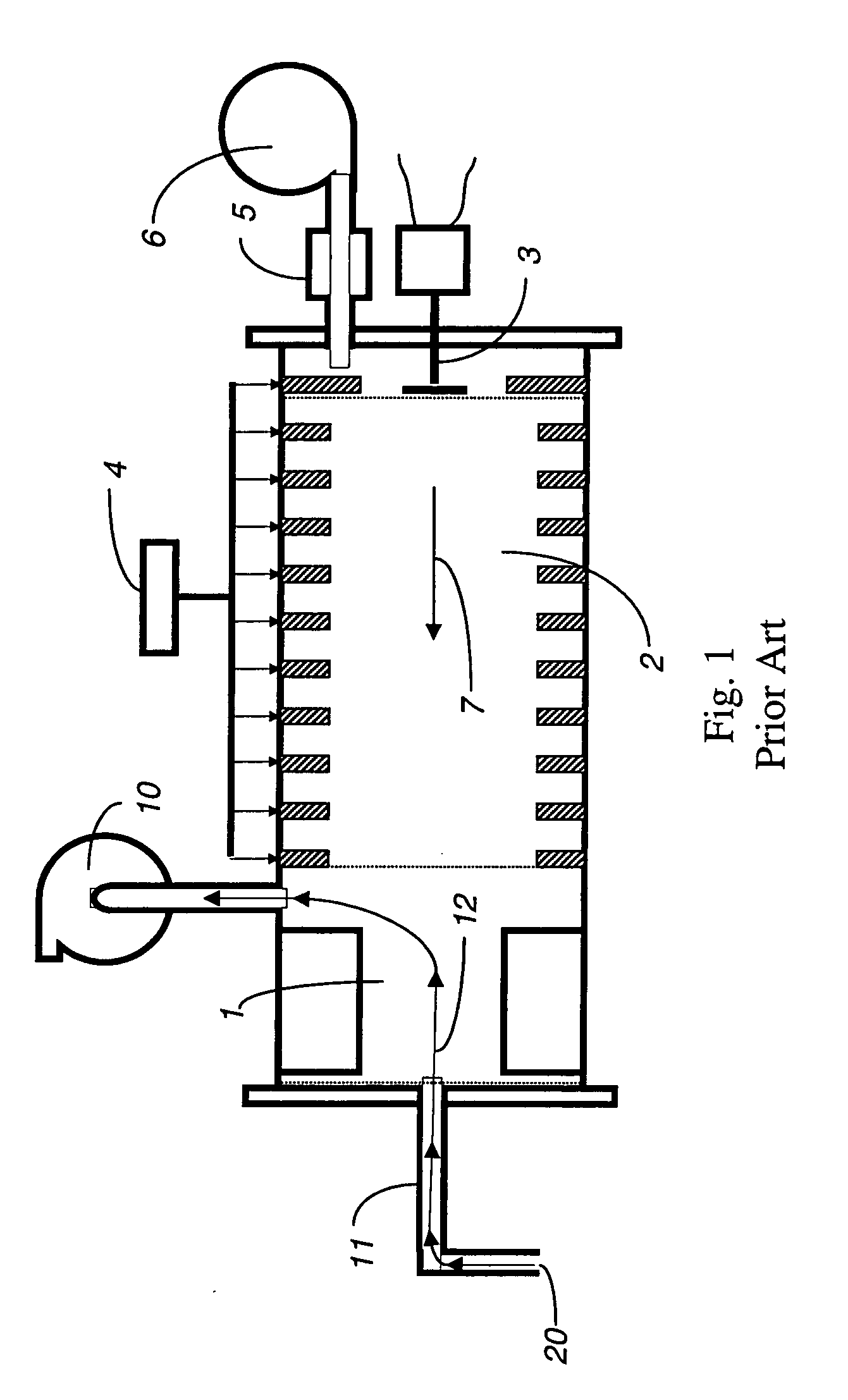
[0026] An IMS is illustrated in FIG. 1. While various embodiments may differ in details, FIG. 1 shows basic features of an IMS that may be used in connection with the system described herein. The IMS includes an ion source 1, a drift tube 2, a current collector 3, a source of operating voltage 4 and a source of purified drift gas 5, possibly with its own gas pump 6. An IMS may already include a gas pump for gas sampling 10 and a tubular connection 11 between the ion source 1 and an external gas sampling inlet 20 that includes an orifice. Gas flow for the drift gas 7 moves through the drift tube 2. Sampling gas flow 12 moves from the external gas sampling inlet 20 through the tubular connection 11 and ion source 1 to the gas sampling pump 10.

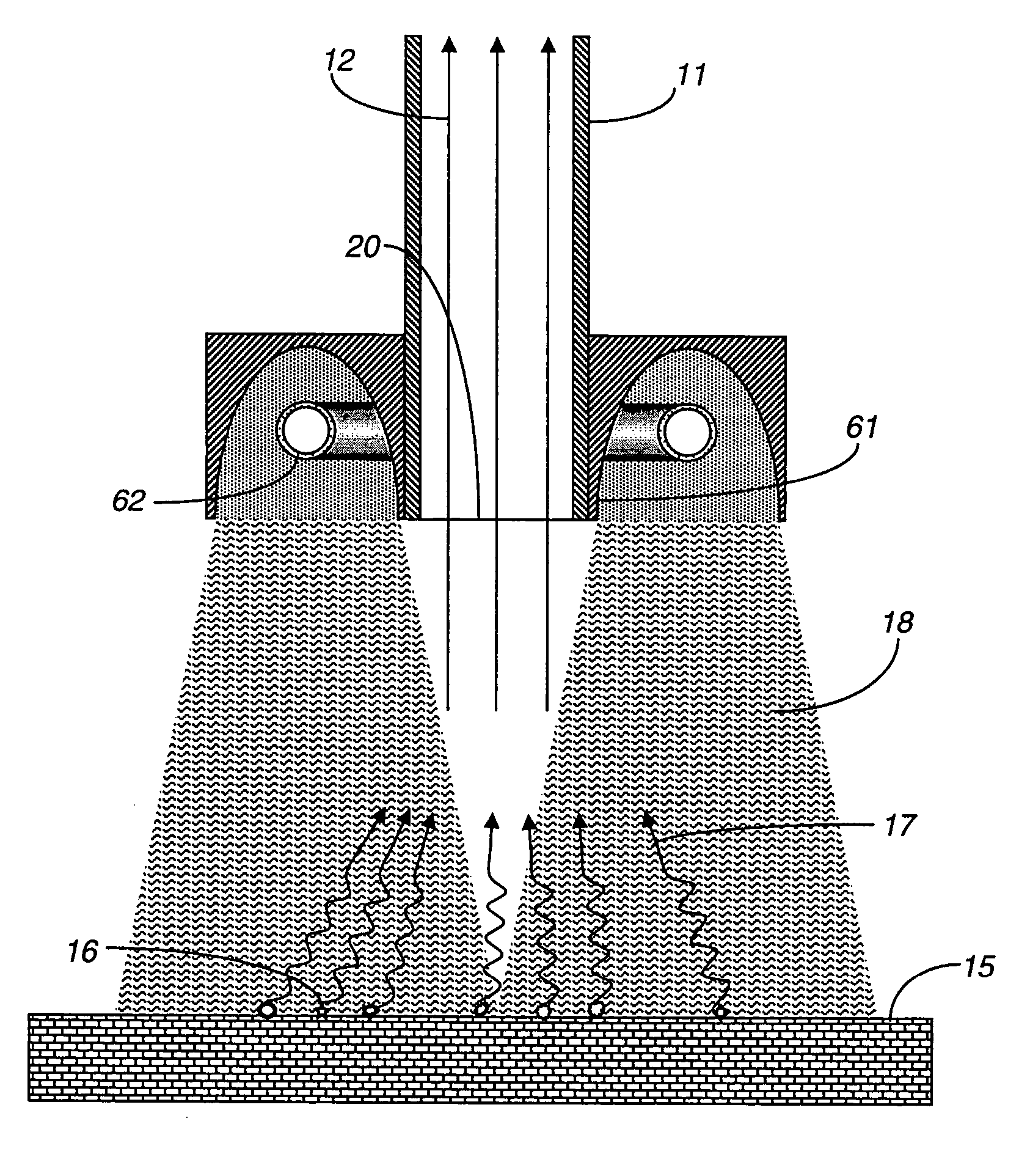
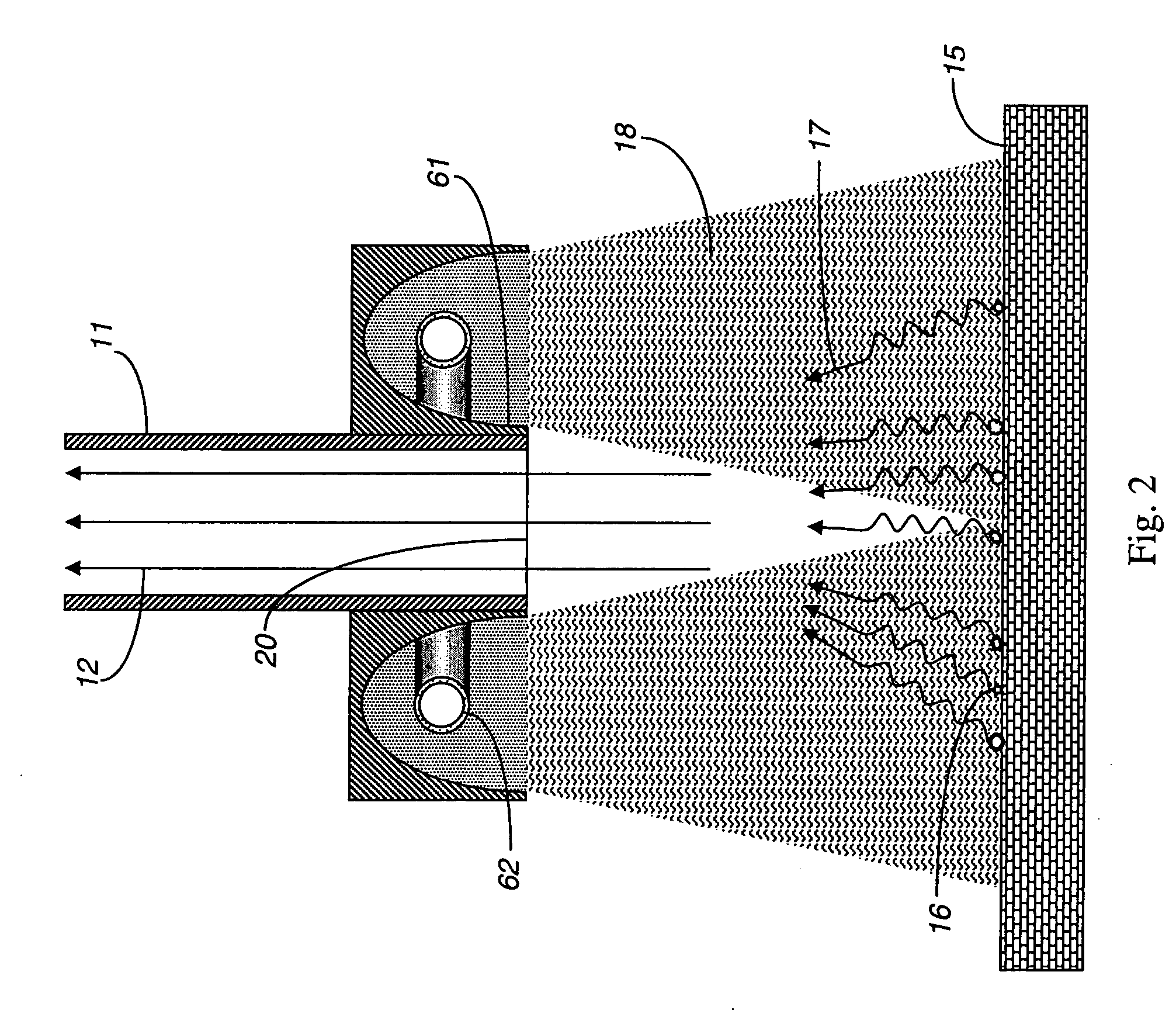
[0027]FIG. 2 shows an exemplary embodiment for a system using an electrical discharge in a gas within a pulsed light lamp 62 provided proximal to the gas sampling inlet 20 that heats the target surface 15 in conjunction with the gas sampling sys...


PUM


Abstract

The presence of trace molecules in air is often determined using high sensitivity gas sensing instruments, such as an ion mobility spectrometer. Such devices are commonly utilized in the fields of explosives detection, identification of narcotics, and in applications characterized by the presence of very low airborne concentrations of organic molecules of special interest. The sensitivity of such instruments is dependent on the concentration of target gas in the sample. The sampling efficiency can be greatly improved when the target object is warmed, even by only a few degrees. A directed emission of photons in the range between infrared and ultraviolet light can be used to significantly enhance vapor emission.

Description

CROSS-REFERENCE TO RELATED APPLICATIONS [0001] This application is a continuation-in-part of U.S. patent application Ser. No. 10 / 349,491 filed on Jan. 22, 2003, which claims priority from U.S. patent application Ser. No. 10 / 295,039 filed on Nov. 14, 2002, which claims priority from U.S. Provisional Application No. 60 / 357,394, filed Feb. 15, 2002, U.S. Provisional Application No. 60 / 357,618, filed Feb. 15, 2002, and U.S. Provisional Application No. 60 / 363,485, filed Mar. 12, 2002, all of which are incorporated herein by reference. This application is also a continuation-in-part of U.S. patent application Ser. No. 10 / 853,563, filed May 25, 2004, which claims priority from U.S. Provisional Patent Application No. 60 / 473,649, filed May 29, 2003, both of which are incorporated herein by reference.FIELD OF THE INVENTION [0002] This invention relates to a trace chemical vapor detection instrument that detects chemicals present as vapors in air or other gases, or liberated as vapors from con...

Claims


Application Information

Patent Timeline
IPC IPC(8): G01N27/62
CPCG01N1/22G01N1/4022G01N27/622B01B1/005G01N2001/028
Inventor BELYAKOV, VLADIMIR V.BUNKER, STEPHEN N.
Owner LEIDOS SECURITY DETECTION & AUTOMATION INC
Why Eureka
Try Eureka