
Plasma sprayed indium tin oxide target for sputtering

Inactive Publication Date: 2005-01-27
LYNN SHANNON
View PDF9 Cites 7 Cited by
  • Summary
  • Abstract
  • Description
  • Claims
  • Application Information

AI Technical Summary

Benefits of technology

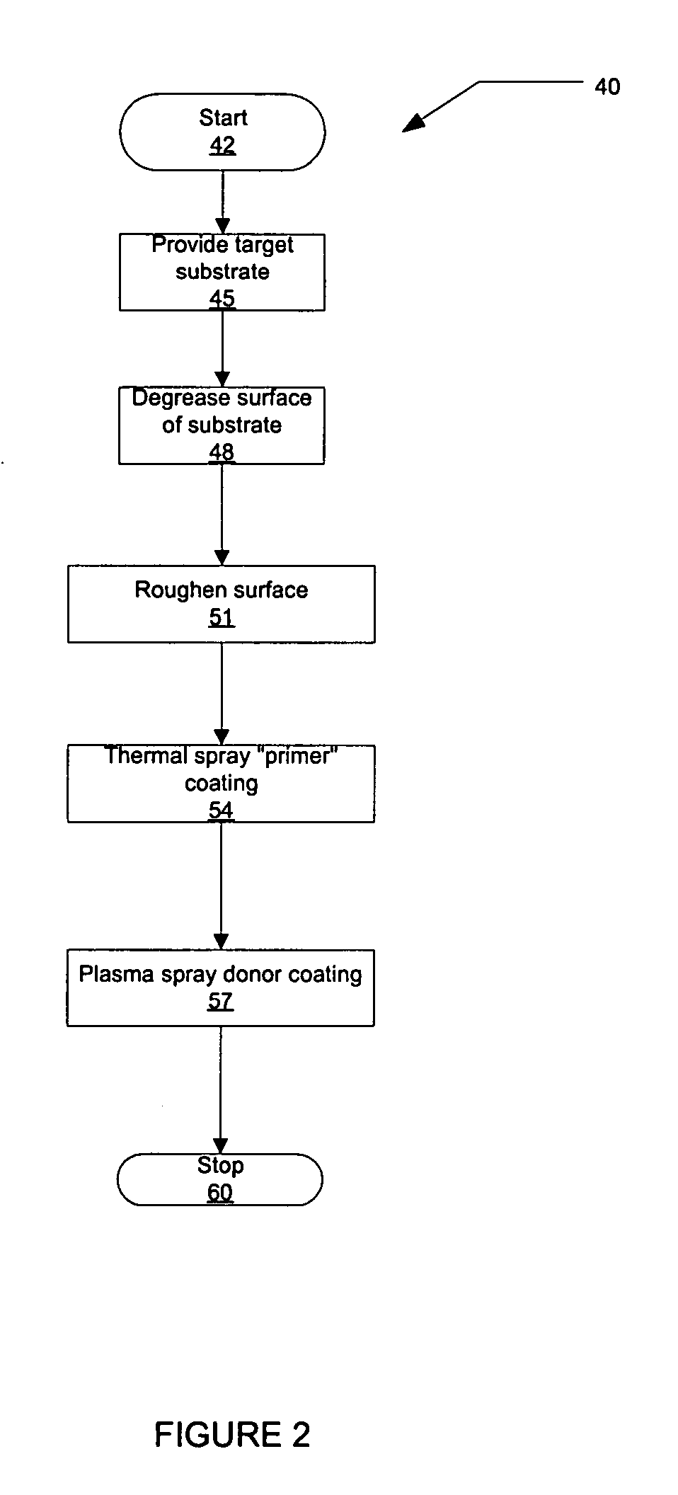
[0012] The present invention provides a method of applying the target donor material coating directly to a prepared metal backing without a separate bonding process. Because the target donor material coating is sprayed rather than bonded as a solid, the coating precisely fits the backing surface. Plasma spraying allows the coating to flow around the backing and into pores of the metal backing. Plasma spraying, therefore, provides improved thermal and electrical conductivity. It also allows the coating to be applied to cylindrically-shaped backing media as well. The resulting targets consistently perform better than conventional targets, allowing for better use of the target donor material coating. Superior connectivity allows less energy to be expended in the process of liberating ions from the target donor material, and also requires the presence of less argon plasma to setup the collisions at the surface of the donor material. As will be readily appreciated from the foregoing summary, the invention provides a method for forming a target for sputtering. The method includes providing a metal target backing. A surface of the provided metal target backing is metalized. A target donor material is plasma sprayed on the portion of the metalized metal target backing.

Problems solved by technology

Any flaws in the bonding could cause arcing, delaminating, or other unwanted effects during the sputtering process.
The physical properties of these compounds preclude the use of anything other than planar backing material due to the difficulty in machining a perfectly matched pair of surfaces.

Method used


Image

  • Plasma sprayed indium tin oxide target for sputtering
  • Plasma sprayed indium tin oxide target for sputtering
  • Plasma sprayed indium tin oxide target for sputtering

Examples


Embodiment Construction

[0016] By way of overview, the present invention provides a method for forming a target for sputtering. The method includes providing a metal target backing. A surface of the provided metal target backing is metalized. A target donor material is plasma sprayed on the metalized metal target backing.

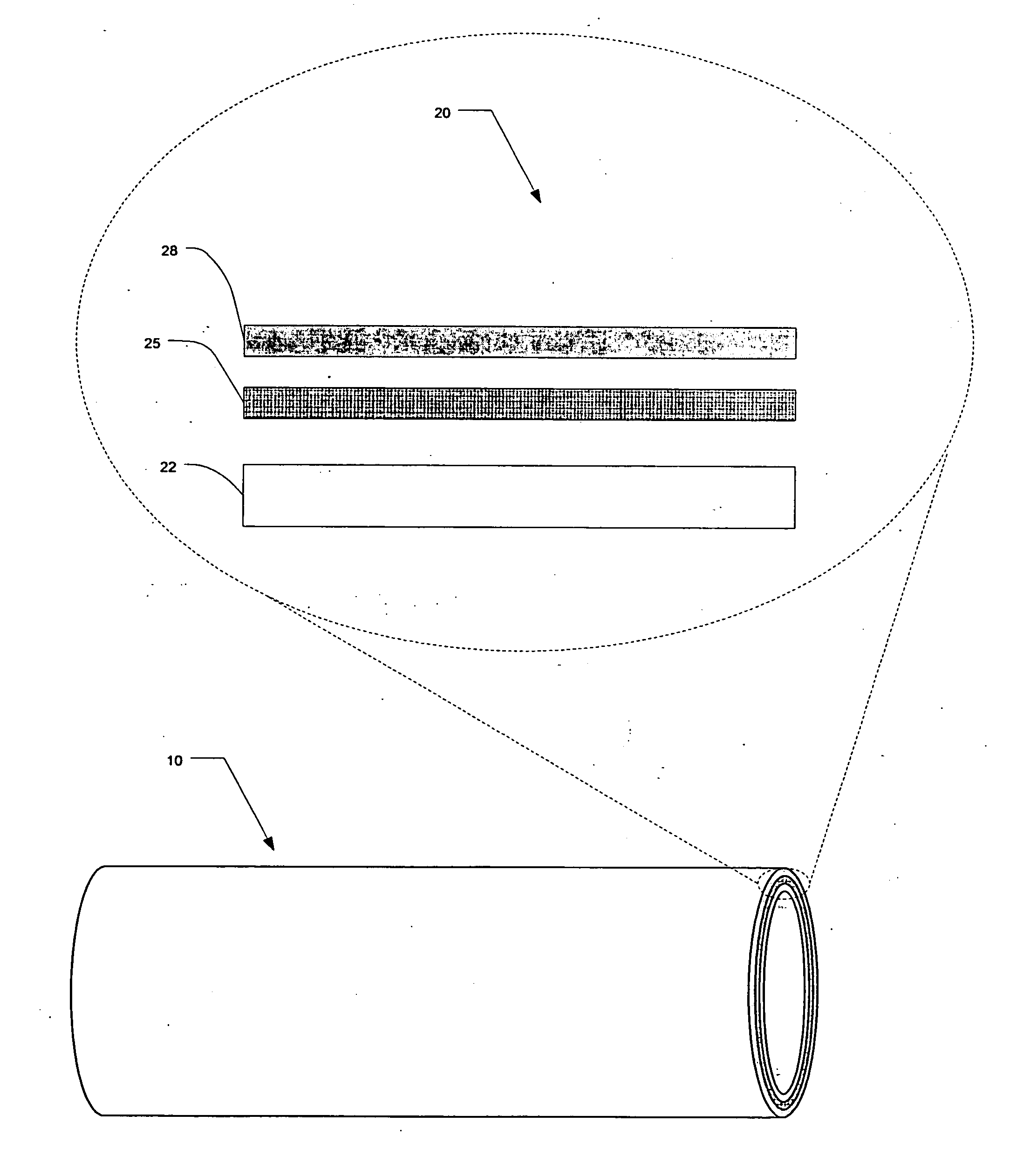
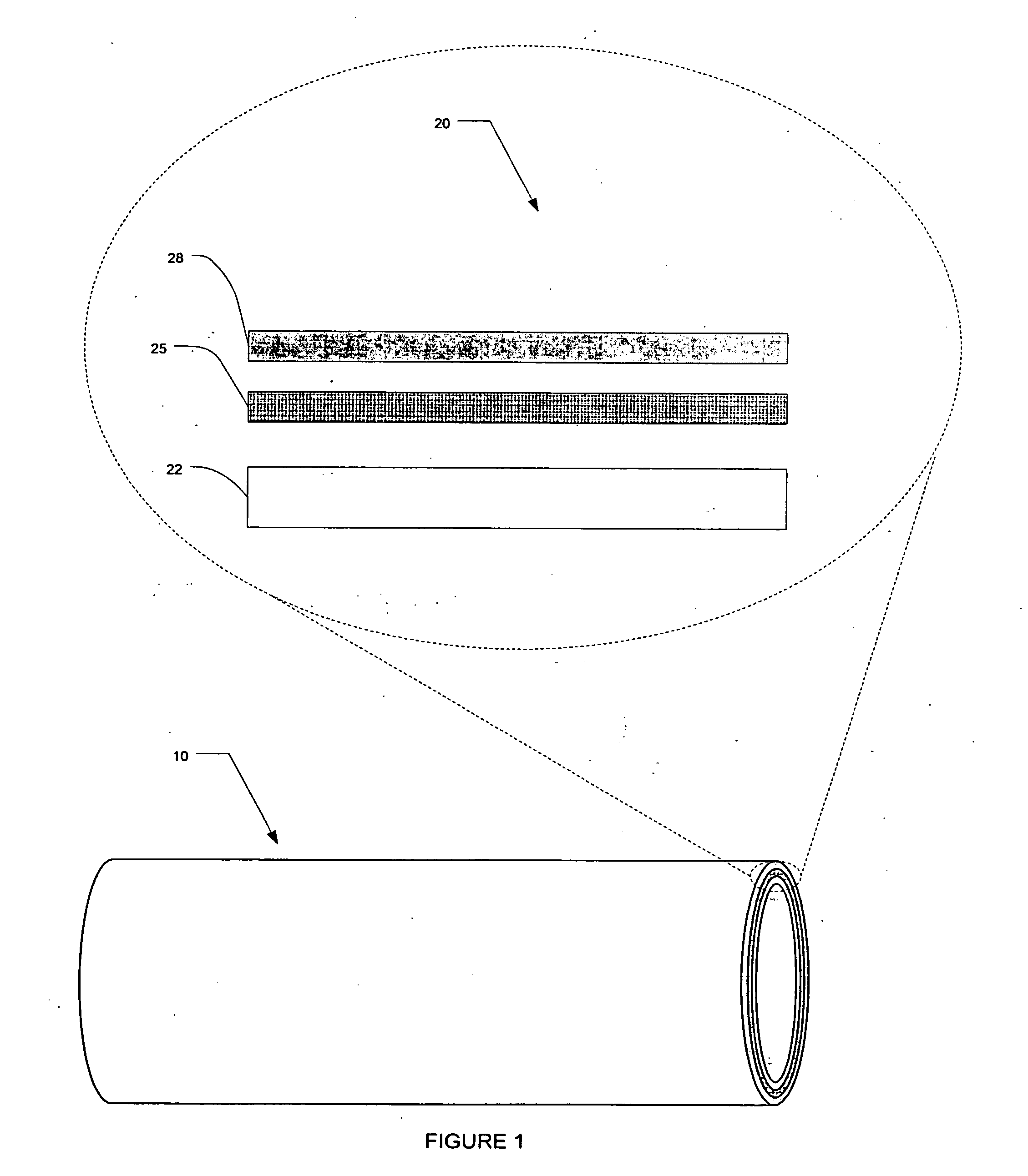
[0017] Referring to FIG. 1, the figure shows a cylindrical sputtering target 10. A cross-section 20 of the sputtering target comprises three layers of material: the substrate 22, the metalizing coating 25, and the target donor material 28. The relative thickness of the three layers of material shown in FIG. 1 is not actual, but is merely for illustrative purposes and not limiting in this disclosure. Additional aspects of a rotating cylindrical magnetron such as an apparatus for attaching the target to a support spindle are disclosed in U.S. Pat. No. 6,375,815, which is incorporated by reference.

[0018] The substrate 22 is also known as the metal backing or metal target backing. The substr...


PUM

PropertyMeasurementUnit
Metallic bondaaaaaaaaaa

Abstract

A method for forming a target for sputtering is provided. The method includes providing a metal target backing. A surface of the provided metal target backing is metalized. A sputtering donor material is plasma sprayed on the metalized metal target backing.

Description

PRIORITY CLAIM [0001] This application claims the benefit of provisional application Ser. No. 60 / 463,857, filed Apr. 17, 2003.FIELD OF THE INVENTION [0002] This invention relates generally to sputtering technology and more specifically, to indium tin oxide (“ITO”) coated sputtering targets. BACKGROUND OF THE INVENTION [0003] Indium oxide doped with tin oxide (“ITO”) is used to make transparent conductive coatings on glass and polymer substrates. Electron-beam evaporation or sputtering deposits thin film layers on suitable substrates. Sputtering is a process that dislodges atoms from the surface of a target material by collision with high-energy particles in order to deposit a metallic film on a substrate. Typical applications of ITO coated substrates include touch panel contacts, electrodes for LCD and electro-chromic displays, energy conserving architectural glass, defogging aircraft and automobile windows, and others. [0004] The existing sputtering process places a thin coating on...

Claims


Application Information

Patent Timeline
IPC IPC(8): C23C14/34
CPCC23C14/3407
Inventor LYNN, SHANNON
Owner LYNN SHANNON
Learn More