Crawler track tension adjusting device

a technology of tension adjustment and track, which is applied in the direction of mechanical equipment, transportation and packaging, and manufacturing, etc., can solve the problems of increasing the load on the coil spring, reducing the efficiency associated with the operation of the work machine, and creating slack, so as to reduce the risk of oil leakage, facilitate machining, and increase the degree of freedom of the vehicle structur

Inactive Publication Date: 2005-02-17
KOMATSU LTD
View PDF13 Cites 39 Cited by
  • Summary
  • Abstract
  • Description
  • Claims
  • Application Information

AI Technical Summary

Benefits of technology

[0020] It is preferable to integrally attach the operating oil tank to the hydraulic pump. The hydraulic circuit including the hydraulic actuator, the direction selector valve and the hydraulic pump has a closed structure in which all the parts are hermetically closed. This structure obviates the need to connect the crawler track tension adjusting device to the hydraulic driving source, which eliminates the use of long hydraulic hoses and therefore markedly reduces the risk of oil leakage caused by vibration or the like. In addition, the crawler track tension adjusting device can be unitized in a small size without use of piping materials such as hydraulic hoses, so that there is no need to take account of a piping space. As a result, the degree of freedom of the vehicle structure increases and machining can be facilitated.
[0021] Further, a stroke sensor for detecting the position of the piston rod may be so disposed as to face an end of the piston rod, which end is opposite to the end facing the yoke. A positional signal issued by the stroke sensor may be input to the controller. This has such an advantage that the tension of the crawler belt can be detected independently of or simultaneously with an issue of a signal by the hydraulic sensor. Additionally, since the stroke sensor is integrally incorporated in the hydraulic actuator, it can be installed in the track frame unsusceptible to contamination with earth and sand and therefore external influences can be eliminated to enable correct signal transmission.
[0022] In the invention, the crawler track tension adjusting device is preferably housed in a casing and two such casings are accommodated in track frames for supporting crawler units, respectively, provided at the right and left sides of the vehicle. Thanks to this arrangement, the crawler track tension adjusting device can be arranged in a compact form and the tension adjusting portion of the crawler belt can be incorporated in a tubular interior part of the track frame of the main frame of a work vehicle equipped with crawler units such as a bulldozer. As a result, the size of the track frame can be reduced, leading to an improvement in the soil removing capability. In contrast with the conventional track adjusters constructed by assembling parts, the crawler track tension adjusting device of the invention is set up as a unit and therefore the efficiency of assembling it into the vehicle body can be remarkably improved. In addition, the parts of the crawler track tension adjusting device are all integrally formed and the device is connected to external parts only through control / driving system wires except the connection to the yoke of the idler. This advantageously simplifies the connection of the crawler track tension adjusting device to the driving system of the vehicle and facilitates maintenance. The crawler track tension adjusting devices provided at the right and left sides can be independently controlled according to the traveling condition of the work machine so as to provide optimum track tension.

Problems solved by technology

The crawler belts are constructed by coupling a plurality of track links and therefore, slack is created because the track link components (e.g., links and bushings) and idlers begin to wear over a period of time.
The use of this track adjuster causes a decrease in the efficiency associated with operation of the work machine.
(2) If a crawler belt bites foreign materials such as rocks during vehicle traveling or if earth and sand penetrate into and deposit on the tooth roots of a driving sprocket, causing abnormal tension on the crawler belt, the load on the coil spring increases, imposing a heavy load on every parts of the track frame.
In view of this, the work machine needs a sturdy structure, which leads to an increase in vehicle weight and therefore additional cost.
The components of the crawler belts are, therefore, required to have enough strength to withstand the impulsive load occurring at that time, which leads to an increase in the weight of the components and therefore additional cost.
(4) Since the size of the coil spring is dependent of the material used, miniaturization of the coils spring is difficult.
This hampers an improvement in the soil removing capability of the work machine.
In addition, it is necessary to run piping from the hydraulic driving source to the undercarriage assembly in which the track adjuster is incorporated, and the space for accommodating the hydraulic piping (mainly hydraulic hoses) is needed, which is accompanied with many problems in manufacturing.
Such a control system is seemingly rational, but imposes the following problem: Since work machines such as bulldozers are usually operated on the unleveled ground and therefore contaminated with earth and sand at their crawler units, the light beam of the sensor is likely to be cut off by earth and sand during operation in cases where a general photoelectric sensor is used as a high-precision positional sensor.
Therefore, such a sensor lacks accuracy.
Even when a bobbin-shaped scale is used as a means for measuring distance in addition to the laser, if earth and sand penetrate into the measuring part during measurement (operation), the measuring function will be hampered, so that intended aims cannot be accomplished.
Therefore, running of hydraulic conduits from the vehicle body to the undercarriage for the purpose of piping from the hydraulic driving system (i.e., the driving source for the track unit and other instruments disposed on the main frame for performing control) to the hydraulic cylinders gives rise to difficulties in reservation of a route, as pointed out earlier.
This causes many problems not only in manufacturing but also in maintenance.

Method used


Image

  • Crawler track tension adjusting device
  • Crawler track tension adjusting device
  • Crawler track tension adjusting device

Examples


first embodiment

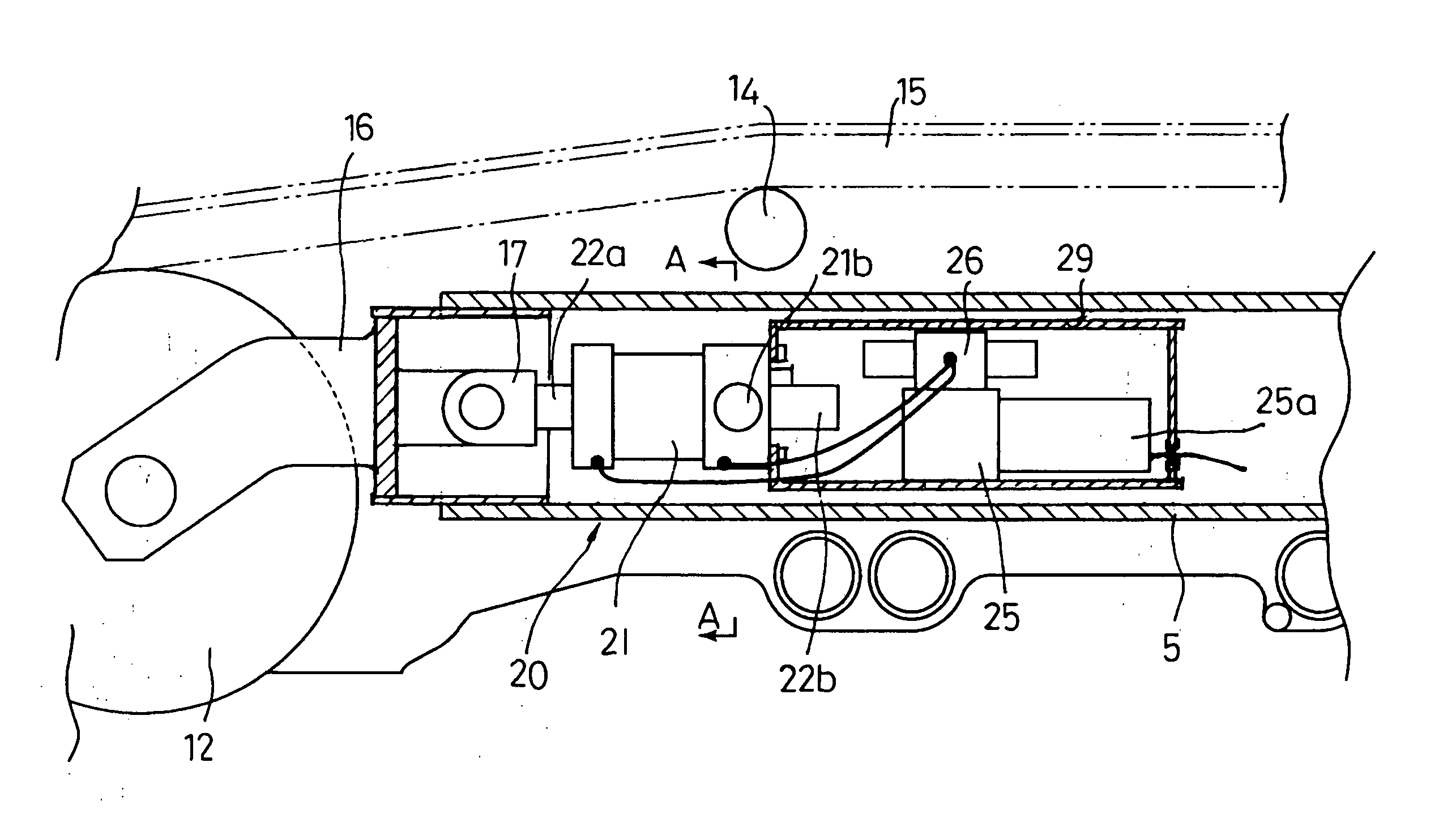
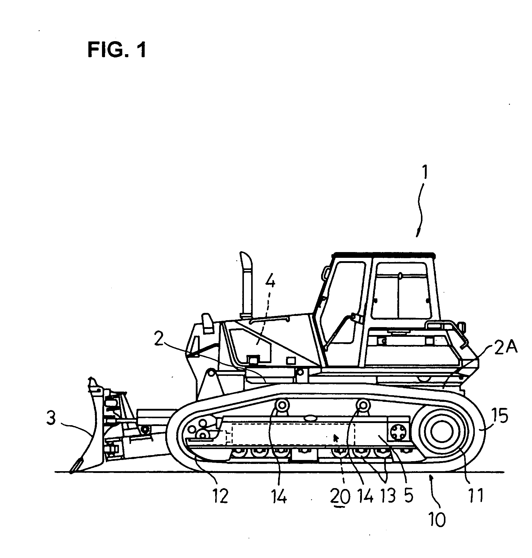
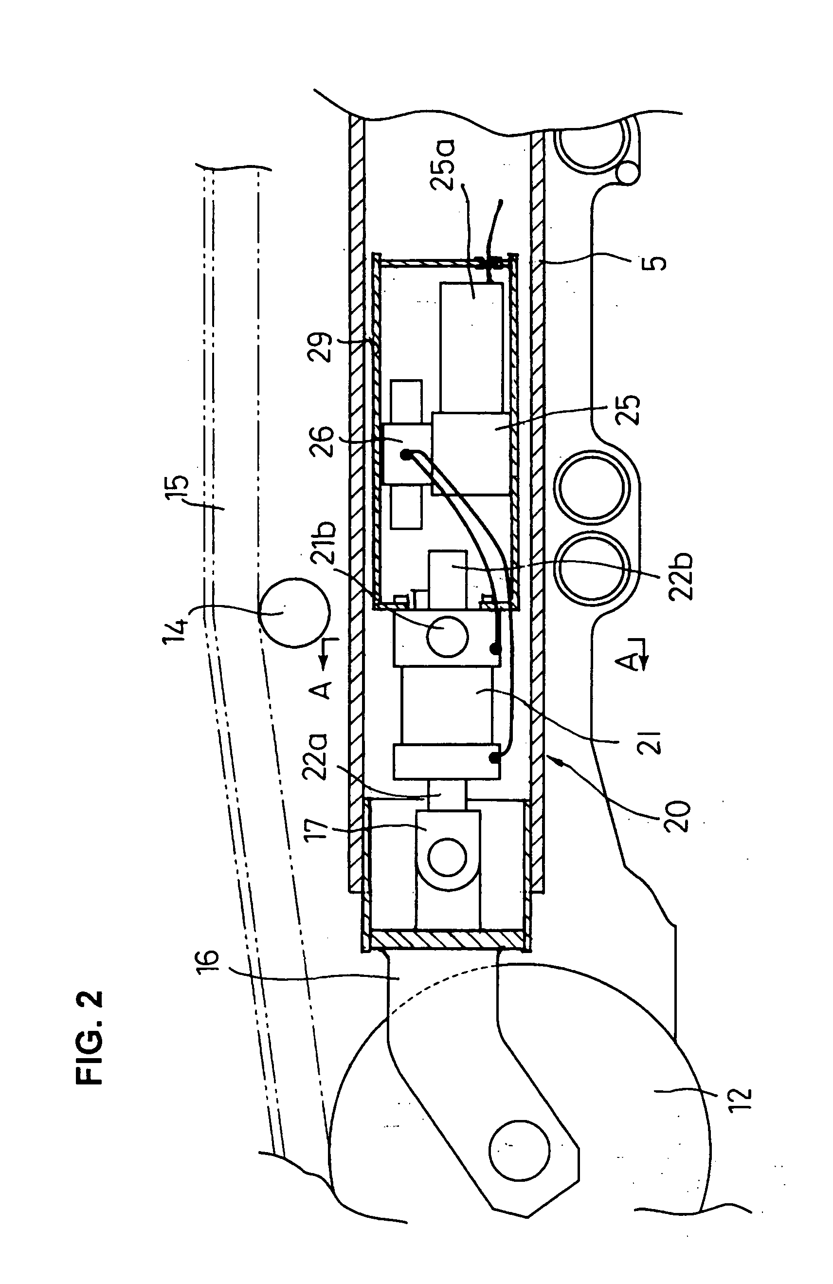
[0030] The first embodiment is associated with a track adjuster which is applied to a bulldozer 1 shown in FIG. 1, the bulldozer 1 serving as a track-type work machine for use in operations such as earth moving and ripping. The bulldozer 1 includes work implements such as a blade 3 and a ripper (not shown) which are operated by a hydraulic drive. In the bulldozer 1, an engine 4 is mounted on a vehicle body 2, for activating the blade 3 and the ripper and making the vehicle move. This bulldozer 1 has a crawler unit 10 on both sides of a main frame 2A.

[0031] Each crawler unit 10 has (i) a driving sprocket 11 located at the rear end of the main frame 2A, (ii) an idler 12 located at the front end, (iii) a plurality of track rollers 13 disposed in the lower part of the intermediate portion, (iv) track carrier rollers 14 disposed in the upper part of the intermediate portion, and (v) an endless crawler belt 15 wrapped around the driving sprocket 11 and the idler 12. The endless crawler be...

second embodiment

[0049] More specifically, the track adjuster 20A of the second embodiment is formed such that discharge ports 40, 41 of the hydraulic pump 25A are connected to an operating oil tank 44 through suction check valves 42, 43 respectively, and the discharge port 40 is connected to the front pressure chamber 23a of the tension adjusting cylinder 21 through the pipe line 28a whereas the discharge port 41 is connected to the rear pressure chamber 23b of the tension adjusting cylinder 21 through the pipe line 28b. In the middle of the pipe line 28b, a check valve 45 is interposed. Extending from the pipe line 28b between the check valve 45 and the rear pressure chamber 23b is a bypass pipe line 28d which is in turn connected to the tank 44. In the bypass pipe line 28d, a relief valve 32 is interposed. Another relief valve 46 is interposed in a pipe line extending from the pressure oil discharge side of the suction check valve 42 to the tank 44.

[0050] In the track adjuster 20A of the second e...


PUM


Abstract

A crawler track tension adjusting device is provided in which a driving unit of a closed structure is used as a control operation mechanism and automatic tension adjustment is carried out in response to a control signal to create optimum tension on a crawler belt. To this end, the crawler track tension adjusting device comprises: (a) a tension adjusting cylinder which is operated in a direction to increase tension and in a direction to reduce tension under the same condition; (b) a hydraulic pump driven by a motor; (c) a hydraulic circuit including an electromagnetic direction selector valve disposed in an oil pipeline for connecting the hydraulic pump to the tension adjusting cylinder; and (d) a hydraulic sensor for detecting the operating condition of the tension adjusting cylinder disposed in the hydraulic circuit. The hydraulic sensor is connected to an additionally installed controller to operate the hydraulic pump and the direction selector valve thereby controlling the tension adjusting cylinder.

Description

TECHNICAL FIELD [0001] The present invention relates to a crawler track tension adjusting device (track adjuster) for adjusting the tension of a crawler track of a track-type work machine such as a bulldozer during traveling. BACKGROUND ART [0002] A known track-type work machine has crawler belts each of which is wrapped around a driving sprocket rotatively driven by a power from a driving source supported by a main frame and around an idler movably supported by the main frame. The crawler belts are each guidingly supported by track rollers at the ground engaging side and by track carrier rollers at the ground unengaging side. For creating tension in the crawler belts, a track tensioning mechanism of the coil spring type or hydraulic cylinder type is interposed between a yoke for supporting a bearing for the idler and a track frame. The crawler belts are constructed by coupling a plurality of track links and therefore, slack is created because the track link components (e.g., links ...

Claims


Application Information

Patent Timeline
Patent Type & Authority Applications(United States)
IPC IPC(8): B62D55/30
CPCB62D55/30
Inventor TAMARU, MASATAKEYAMAMOTO, TEIJIYAMAMOTO, SHIGERU
Owner KOMATSU LTD
Why Eureka
Try Eureka