Inorganic compound particle and process for preparation thereof

a technology of organic compound and film, which is applied in the field of organic compound particles, can solve the problems of difficult to fix the particles onto the substrate surface or form a single layer film, control the surface reflectance, and high cost, and achieve low cost and high hydrophobicity. , the effect of low shrinkage property

Inactive Publication Date: 2005-02-17
JGC CATALYSTS & CHEM LTD
View PDF12 Cites 11 Cited by
  • Summary
  • Abstract
  • Description
  • Claims
  • Application Information

AI Technical Summary

Benefits of technology

The present invention intends to provide a substrate coated with a transparent coating film, containing specified inorganic compound particles and a specified fluorine-containing silicone, which has low reflectivity, low shrinkage property, and high hydrophobicity, and which is excellent in adhesiveness to the substrate or the transparent electroconductive layer (transparent electroconductive coating film) when the layer is formed, film strength, chemical resistance, and like properties. The present invention intends also to provide a coating liquid suitable for formation of the above transparent film, and a display device employing the transparent film coated substrate being excellent in anti-static properties and electromagnetic wave shielding properties.

Problems solved by technology

However, such methods are costly.
However, with this method, it is not easy to fix the particles onto the substrate surface or to form a single layer film thereof on the surface of the substrate and to control the surface reflectance.
The aforementioned transparent films, however, are not sufficient in scratch resistance, being liable to be scratched at the surface to become inferior in the transparency or the antireflection property of substrate.
However, in the aforementioned electroconductive coating films formed on substrate, the fine metal particles contained therein can be oxidized, can grow to larger particles by metal ionization, or can be corroded.
Thereby, the electroconductivity or light transmittance of the coating film may be decreased, which lowers the reliability of the display apparatus.
Further, the electroconductive oxide particles and fine metal particles contained in the electroconductive coating film have high refractivity, which causes reflection of light, disadvantageously.
On the other hand, when a conventional transparent coating film containing a matrix composed of silica or the like is formed on the electroconductive film surface, the density of the electroconductive film is liable to become nonuniform owing to the difference in the shrinkage degree between the transparent film and the electroconductive film.
As a consequence, failure of electrical contact between the electroconductive fine particles may result and insufficient overall electroconductivity of the film may develop.
Furthermore, in the heat treatment, the transparent coating film is not sufficiently densified and is porous so as to form cracks and voids, which may permit penetration of moisture and chemicals such as acids and alkalis, all of which are disadvantages.
An acid or alkali which penetrates into the transparent coating film may react with the surface of the substrate to lower the refractivity, or may react with the fine particles of the metal or the like in the formed electroconductive coating film, when it is employed, to lower the chemical resistance of the coating film and to decrease the anti-static property and electromagnetic wave shielding effect of the electroconductive film, disadvantageously.
This makes the visual feeling of the image reflection (mirror reflection) stronger, and the coloration of the reflected light cannot readily be suppressed.

Method used


Image

  • Inorganic compound particle and process for preparation thereof
  • Inorganic compound particle and process for preparation thereof
  • Inorganic compound particle and process for preparation thereof

Examples


preparation example 1

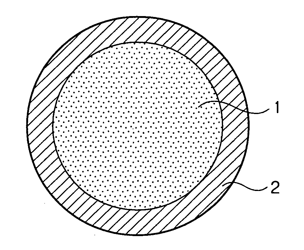
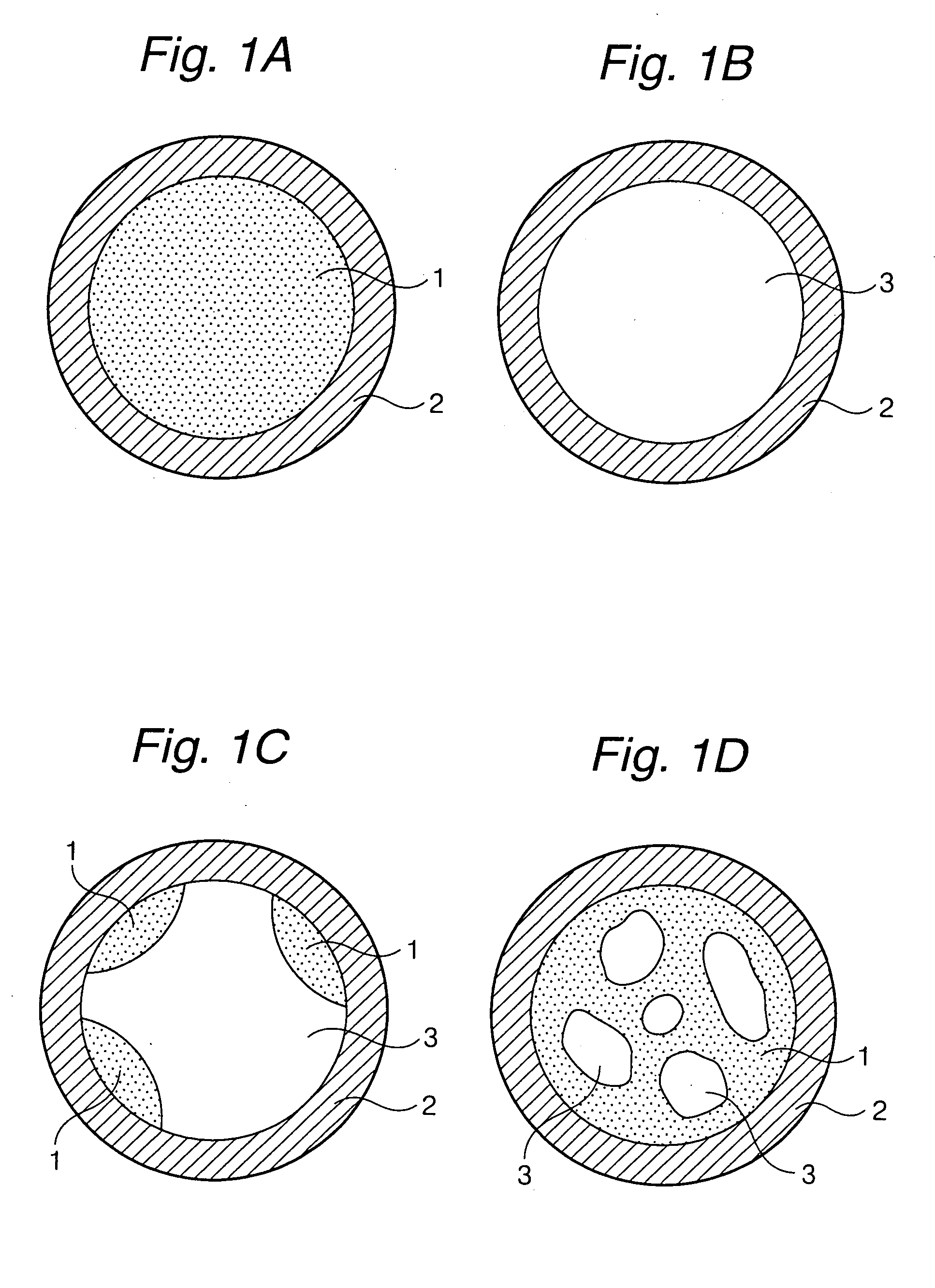
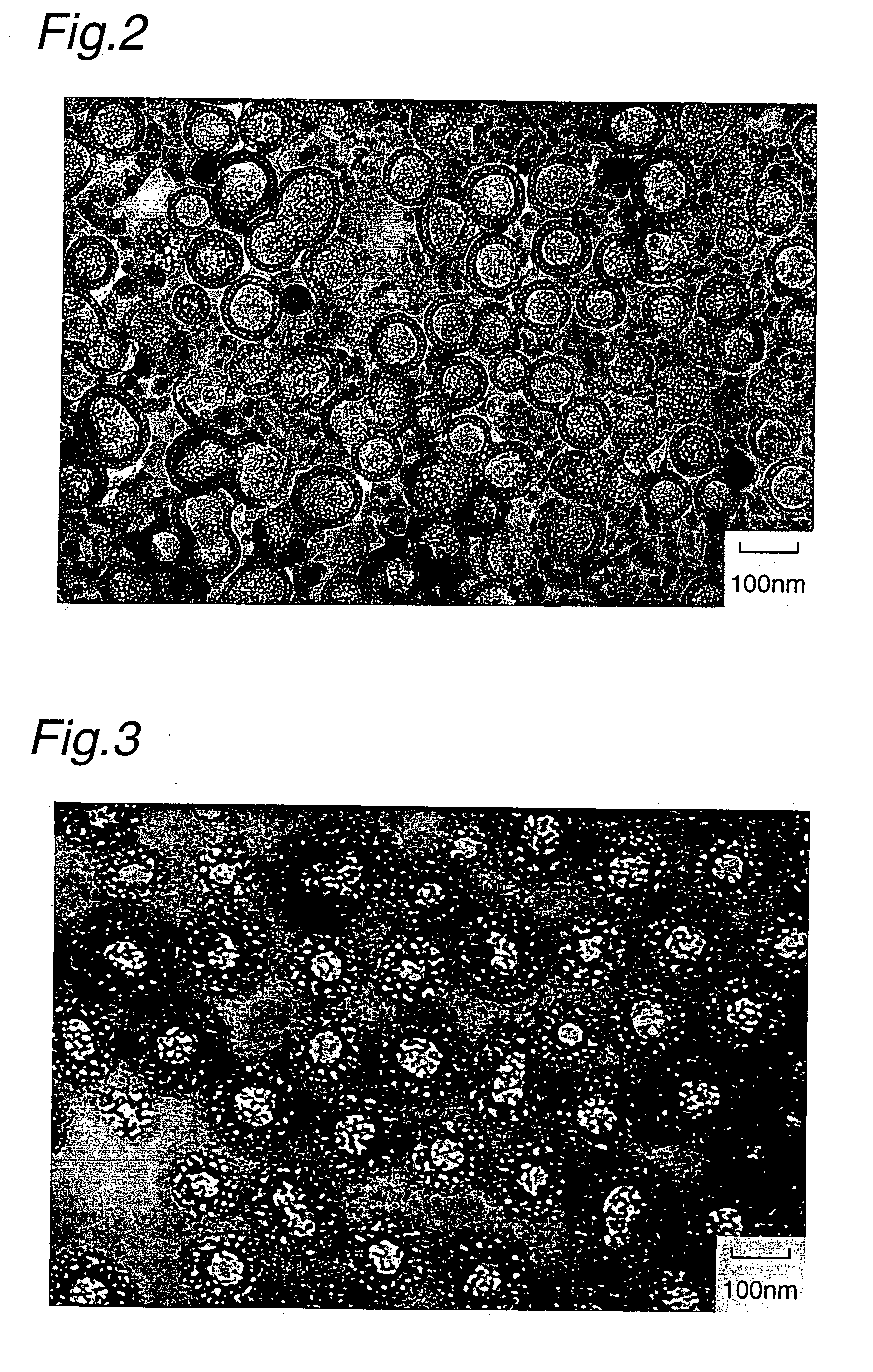
Preparation of Inorganic Compound Particle P-1 (Porous Matter Enclosed by Shell)

A 100 g portion of silica sol having average particle diameter of 5 nm and containing SiO2 at a concentration of 20% by weight, and 1,900 g of pure water were mixed to prepare a reaction mother liquor. The mother liquor was heated to 80° C. The mother liquor had a pH of 10.5. To the mother liquor were added simultaneously 9,000 g of aqueous sodium silicate solution (1.5% by weight in terms of SiO2) and 9,000 g of sodium aluminate (0.5% by weight in terms of Al2O3) by keeping the temperature at 80° C. The pH of the reaction solution rose to 12.5 immediately after the addition of the sodium silicate and the sodium aluminate, and was nearly constant thereafter. After completion of the addition of the solutions, the reaction liquid was cooled to room temperature and washed by ultrafiltration to obtain a liquid dispersion (A) of a porous material precursor particle containing SiO2.Al2O3 at a solid matter c...

preparation example 2

Preparation of Inorganic Compound Particle P-2 (Porous Matter Enclosed by Shell)

To 10 g of the liquid dispersion (A) of the porous material precursor particle obtained above, 1,900 g of pure water was added and the mixture was heated to 95° C. By keeping this temperature, 27,000 g of an aqueous sodium silicate solution (1.5% by weight in terms of SiO2), and 27,000 g of an aqueous sodium aluminate solution (0.5% by weight in terms of Al2O3) were added gradually concurrently to grow particles by utilizing, as seed, the particles of the liquid dispersion (A) of the porous material precursor particle. After completion of the addition, the mixture was cooled to room temperature, and washed and concentrated by ultrafiltration to obtain a liquid dispersion (C) of a porous material precursor particle containing SiO2.Al2O3 at a solid matter concentration of 20% by weight. (Step 1)

A 500 g portion of this liquid dispersion (C) of the porous material precursor particle was treated in the s...

preparation example 3

Preparation of Inorganic Compound Particle P-3 (Porous Matter Enclosed by Shell)

To 10 g of the liquid dispersion (C) of the porous material precursor particle obtained above, 1,900 g of pure water was added and the mixture was heated to 95. By keeping this temperature, 7,000 g of an aqueous sodium silicate solution (1.5% by weight in terms of SiO2), and 7,000 g of an aqueous sodium aluminate solution (0.5% by weight in terms of Al2O3) were added gradually concurrently to grow particles. After completion of the addition, the mixture was cooled to room temperature, and washed and concentrated by ultrafiltration to obtain a liquid dispersion (D) of a porous material precursor particle containing SiO2.Al2O3 at a solid matter concentration of 13% by weight.

To 500 g of this liquid dispersion (D) of the porous material precursor particle, 1,125 g of pure water was added, and thereto hydrochloric acid (35.5%) was added dropwise to adjust the pH to 1.0. The liquid mixture was treated fo...


PUM

PropertyMeasurementUnit
particle diameteraaaaaaaaaa
thicknessaaaaaaaaaa
molar ratioaaaaaaaaaa

Abstract

Inorganic compound particles constituted of a shell, a porous matter or a cavity enclosed therein, and the porous matter or the cavity being kept unchanged in a subsequently formed transparent coating film.

Description

BACKGROUND OF THE INVENTION 1. Field of the Invention The present invention relates to a substrate coated with a transparent film, a coating liquid for forming the transparent film, and a display device employing the substrate coated with the transparent film. More specifically, the present invention relates to a substrate coated with a transparent film, which has high strength, and is excellent in antireflection property, anti-static property, electromagnetic wave-shielding property, durability, water-resistance, chemical resistance, and in particular excellent in scratch resistance. The present invention relates also to a coating liquid suitable for the transparent film formation, and a display device having a front face plate constructed of the substrate coated with the transparent film. 2. Description of the Prior Art For prevention of reflection at the surface of a substrate such as a glass plate, and a plastic sheet, an antireflection film is formed thereon. For example, a...

Claims


Application Information

Patent Timeline
Patent Type & Authority Applications(United States)
IPC IPC(8): C03C17/00C03C17/34C03C17/36
CPCC03C17/007Y10T428/2991C03C17/36C03C17/3655C03C17/3676C03C2217/425C03C2217/445C03C2217/475C03C2217/76C03C2217/78Y10T428/2984Y10T428/2996Y10T428/2995Y10T428/25Y10T428/2982Y10T428/2993Y10T428/2998C03C17/34Y10T428/249953Y10T428/249998Y10T428/249962C03C17/30
Inventor HIRAI, TOSHIHARUNISHIDA, HIROYASUKOMATSU, MICHIO
Owner JGC CATALYSTS & CHEM LTD
Why Eureka
Try Eureka