Magnetoresistance effect element

a technology of magnetic coupling and effect element, applied in the field of magnetic resistance effect element, can solve the problems of weakened magnetic coupling via the nol, difficult to insert a nol into a pinned layer to maintain a high specular rate, and not so good specular ra

Inactive Publication Date: 2005-03-03
KK TOSHIBA
View PDF16 Cites 11 Cited by
  • Summary
  • Abstract
  • Description
  • Claims
  • Application Information

AI Technical Summary

Benefits of technology

[0024] It is therefore an object of the present invention to eliminate the aforementioned problems and to realize a magnetoresistance effect element having a high sensitivity and a high reliability.

Problems solved by technology

However, it is very difficult to insert a NOL into a pinned layer to maintain a high specular rate while holding a magnetically sufficient strong coupling of top and bottom pinned layers via the NOL.
For example, when oxygen gas is caused to flow to form a NOL, if the oxygen exposure amount is increased at an oxidizing step of forming the NOL in order to obtain a high specular rate, there is a problem in that the magnetic coupling via the NOL is weakened whereas the specular rate is not so improved.
Inversely, if oxidation is carried out at a weak oxygen exposure amount, there is a problem in that the magnetic coupling of the top and bottom pinned layers via the NOL increases whereas a high specular rate is not obtained and the rate of change in MR is not so improved.
However, since no energy is applied in the oxidizing process, the control range of physical properties of a NOL capable of being formed is narrow, and the control range in the process is also very narrow.
However, since the surface of a sample is exposed to suspended oxygen before oxygen plasma is fired (produced), there is a problem in that an oxide film is formed by simple oxygen gas, so that the same layer as a natural oxide film is formed in the portion of an initially grown NOL.
Although it is possible to carry out a high energy oxidation by plasma energy, there is a problem in that the portion of the initially grown NOL is always influenced by a natural oxide film based on suspended oxygen.
As described above, in the case of the natural oxidizing method, the controllability of the oxygen exposure amount from the low flow amount of oxygen to the high flow amount of oxygen is relatively excellent, whereas it is not possible to obtain a high specular rate since no energy is applied during oxidation.
On the other hand, the IBO, the radical oxidation and the plasma oxidation are effective in a high energy oxidation, whereas there are problems in that it is not sufficiently control the amount of oxygen so that it is not possible to control a low amount of oxygen and that a natural oxide film is also formed as an initially grown NOL.
However, in the conventional high energy process, it is difficult to control a low amount of oxygen, and the initially grown NOL always becomes a natural oxide film.
In such a case, the electron reflective effect decreases, so that it is not possible to sufficiently increase the MR.
Moreover, the quality of NiO is not so sufficiently good unless its thickness is about more than 10 nm, that the increase of the MR based on the electron reflective effect is small.
From this point of view, it is difficult to use the above described electron reflective layer having a thickness reaching 10 nm for a device.
These greatly cause to reduce the electron reflective effect, cause deterioration of output, and cause deterioration of long-term thermal stability.
As described above, in the conventional structure wherein the oxide electron reflective layer is stacked on the side of the free layer, the MR is improved, whereas there are many problems as a device which is put to practical use, so that it is difficult to put the device to practical use.

Method used


Image

  • Magnetoresistance effect element
  • Magnetoresistance effect element
  • Magnetoresistance effect element

Examples


first embodiment

[0118] First, as the first embodiment of the present invention, an example for applying a NOL based on oxidation at a small amount of oxygen using an IAO oxidation, to a magnetoresistance effect element having a spin-valve structure will be described below.

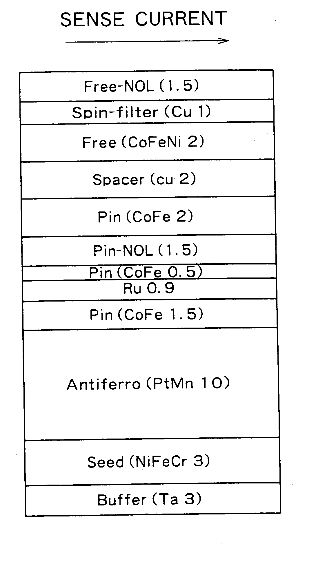
[0119] In this embodiment, a NOL-SPSV (NOL-specular reflection spin-valve) film having the following stacked structure was formed. A numeral in parentheses for each of layers denotes the thickness (nanometer) of the film.

Ta (2 nm)Cap LayerTaOReflective LayerCu (1 nm)High Conductive LayerCoFeNi (2 nm)Free LayerCu (2.2 nm)Non-magnetic Intermediate LayerCoFe (2 nm)Pinned layer {circle over (2)}NOLNOLCoFe (1 nm)Pinned layer {circle over (1)}PtMn (10 nm)Antiferromagnetic LayerNiFeCr (5 nm)Underlying Film {circle over (2)}Ta (3 nm)Underlying Film {circle over (1)}SubstrateSubstrate

[0120] In an actual head, an “alutic substrate” wherein amorphous alumina is coated on a shielding film is used as a substrate. However, a thermally oxidiz...

second embodiment

[0190] The second embodiment of the present invention will be described below. This embodiment relates to a process sequence when oxygen is fed to an ion source in an oxidizing chamber.

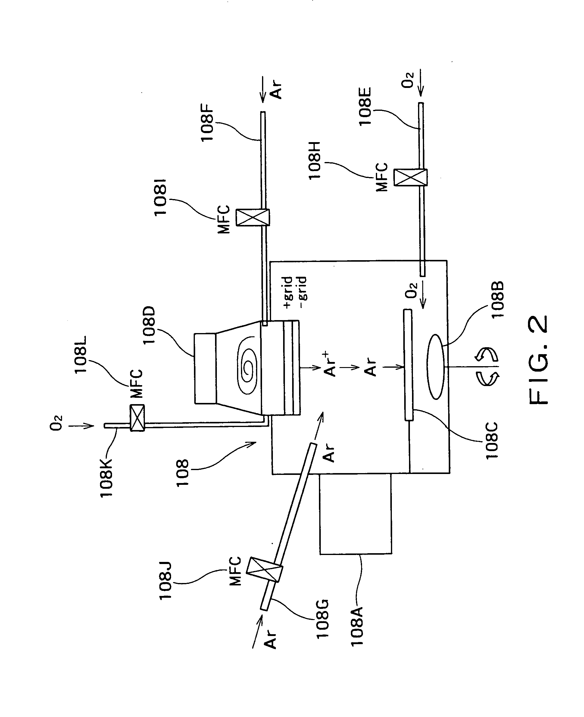
[0191]FIG. 6 is a conceptual drawing showing the construction of an oxidizing chamber capable of being used in this embodiment.

[0192]FIG. 7 is a flow chart showing a sequence of an oxidizing process which is carried out by using the oxidizing chamber of FIG. 6.

[0193] In FIGS. 6 and 7, the same reference numbers are given to the same elements as those which have been described above with respect to FIGS. 2 through 4, and the detailed descriptions are omitted.

[0194] As shown in FIG. 6, in the oxidizing chamber 108 in this embodiment, the oxygen feed system 108E is connected to the ion source 108, so that oxygen containing ions can be produced.

[0195] When such an oxidizing chamber 108 is used for carrying out the conventional IBO method, it is a first object to irradiate with oxygen plasma, so that ...

third embodiment

[0204] The third embodiment of the present invention will be described below. This embodiment relates to a process sequence when oxygen is fed in an oxidizing chamber having no independent ion source.

[0205]FIG. 8 is a conceptual drawing showing the construction of an oxidizing chamber capable of being used in this embodiment.

[0206]FIG. 9 is a flow chart showing a sequence of an oxidizing process which is carried out by using the oxidizing chamber of FIG. 8.

[0207] In FIGS. 8 and 9, the same reference numbers are given to the same elements as those which have been described above with respect to FIGS. 2 through 7, and the detailed descriptions are omitted.

[0208] As shown in FIG. 8, the oxidizing chamber 108 in this embodiment has no independent ion source. In place thereof, plasma is produced in the oxidizing chamber by means of a plasma producing electrode 108M which is connected to a plasma producing power supply 108L. The oxidizing chamber 108 is connected to an oxygen feed sys...


PUM

PropertyMeasurementUnit
thicknessaaaaaaaaaa
thicknessaaaaaaaaaa
thicknessaaaaaaaaaa

Abstract

There are provided a magnetoresistance effect element, a magnetic head, a magnetic head assembly and a magnetic recording system, which have high sensitivity and high reliability. The magnetoresistance effect element has two ferromagnetic layers, a non-magnetic layer provided between the ferromagnetic layers, and a layer containing an oxide or nitride as a principal component, wherein the layer containing the oxide or nitride as the principal component contains a magnetic transition metal element which does not bond to oxygen and nitrogen and which is at least one of Co, Fe and Ni.

Description

CROSS REFERENCE TO RELATED APPLICATION [0001] This application is based upon and claims benefit of priority from the prior Japanese Patent Applications No. 2000-268934, filed on Sep. 5, 2000; and No. 2000-269099, filed on Sep. 5, 2000; the contents of which are incorporated herein by reference. BACKGROUND OF THE INVENTION [0002] 1. Field of The Invention [0003] The present invention relates generally to a magnetoresistance effect element, a method and system for fabricating the same, and a magnetic reading system using the same. More specifically, the invention relates to a magnetoresistance effect element using a spin-valve film having an oxide layer or a nitride layer as a magnetoresistance effect improving layer for causing a specular reflection of electrons, a method and system for fabricating the same, and a magnetic reading system using the same. [0004] 2. Description of Related Art [0005] In order to realize the enhancement of the density of hard disk drives (HDDs), a giant m...

Claims


Application Information

Patent Timeline
Patent Type & Authority Applications(United States)
IPC IPC(8): G11B5/39H01F10/32
CPCB82Y10/00B82Y25/00G11B5/3903G11B2005/3996H01F10/3272H01F41/325H01L43/10Y10T428/1121Y10T428/1114H01F10/3295H01F10/3259H01L43/08G11B5/3932H10N50/85H10N50/10
Inventor FUKUZAWA, HIDEAKIKOI, KATSUHIKOFUKE, HIROMITOMITA, HIROSHIIWASAKI, HITOSHISAHASHI, MASASHI
Owner KK TOSHIBA
Why Eureka
Try Eureka