Exhaust gas treatment catalyst and exhaust gas treatment method

a technology of exhaust gas treatment and catalyst, which is applied in the direction of physical/chemical process catalysts, fluid couplings, separation processes, etc., can solve the problems of increasing the frequency of filter regeneration, affecting the efficiency of exhaust gas treatment, and the inability to properly ignite and burn accumulated particulates, etc., to achieve effective removal of particulates and nitrogen oxides, excellent resistance to sulfur poisoning, and high oxygen concentration

Active Publication Date: 2005-03-03
MITSUBISHI HEAVY IND ENGINE & TURBOCHARGER LTD
View PDF7 Cites 24 Cited by
  • Summary
  • Abstract
  • Description
  • Claims
  • Application Information

AI Technical Summary

Benefits of technology

To solve the above-described problems, the inventors conducted studies earnestly to develop an exhaust gas treatment catalyst that can effectively remove particulates and nitrogen oxides contained in exhaust gas with a high oxygen concentration that is discharged from a diesel engine etc., and also is excellent in resistance to sulfur poisoning as necessary. Also, the inventors studied an exhaust gas treatment catalyst that is low in cost because it does not contain a noble metal as a principal component, and can efficiently remove carbon monoxide and hydrocarbon in addition to nitrogen oxides in engine exhaust gas with excess oxygen and an exhaust gas treatment method using the said catalyst. As a result, the inventors found that the above-described problems can be solved at once by using a catalyst system containing a particular compound oxide expressed by a general formula of AMxOy. The present invention has been completed from this point of view.

Problems solved by technology

In recent years, particulate carbon substances, NOx, etc. in exhaust gas discharged from diesel engines or the like have gained notoriety as being harmful to environmental protection and health, and have thus been regulated.
In the case of the former method, pressure loss increases as the particulate removing effect is enhanced, so that the frequency of filter regeneration increases, which is thought to be economically disadvantageous.
Under such exhaust gas conditions, an exhaust gas treatment filter regenerating method has not yet been established in which accumulated particulates are ignited and burned properly without the occurrence of secondary pollution.
However, when the exhaust gas has a high temperature above 900° C., the catalyst has poor long-term heat resistance.
Also, in exhaust gas treatment methods using other catalysts, it is difficult for NOx in exhaust gas that has a high oxygen concentration to be removed efficiently without introducing hydrocarbon.
Thus, a method for effectively removing harmful components including NOx has not yet been established.
On the rich side, the removal of NOx using a catalyst is relatively easy, but on the lean side, the removal of NOx is difficult because of the inactive oxidizing action.
Also, exhaust gas discharged from a diesel engine is always under conditions on the lean side, so that it is difficult for NOx to be removed.
However, even if the quantity of carried platinum is increased in the atmosphere with excess oxygen, it cannot be said that this catalyst has a practically sufficient NOx removal efficiency.
However, this NOx removing method has problems of high cost due to the use of noble metal and deteriorated performance due to sulfur (SOx) poisoning.
However, it cannot be said that either of these methods has sufficient NOx removal performance.

Method used


Image

  • Exhaust gas treatment catalyst and exhaust gas treatment method
  • Exhaust gas treatment catalyst and exhaust gas treatment method
  • Exhaust gas treatment catalyst and exhaust gas treatment method

Examples


example

Example 1

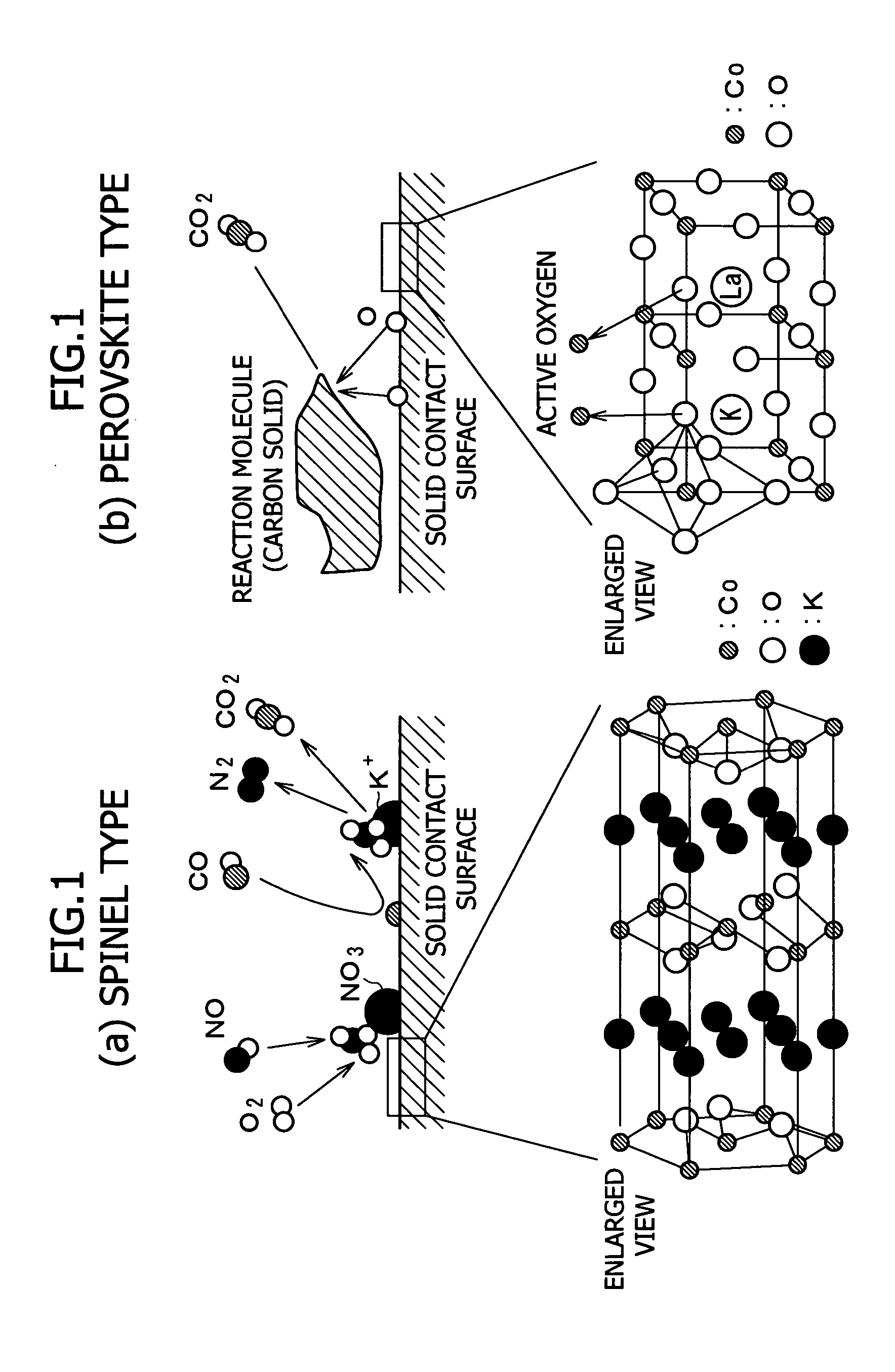
[Synthesis of Catalyst Containing Compound Oxide of General Formula (1)]

34 grams of K2CO3 and 16 grams of CoO were put in a dispersing agent and 50 grams of ethanol, and were ground and mixed in a ball mill for 20 hours. The obtained slurry was dried at 120° C. for 24 hours, and the produced powder was fired in the air at 850° C. for 10 hours to obtain catalyst A.

example 2

[Synthesis of Catalyst Containing Compound Oxide of General Formula (1) and Perovskite Compound Oxide of General Formula (2)]

13.7 grams of K2CO3, 21.3 grams of CoO, and 16.2 grams of La(OH)3 were put in a dispersing agent and 50 grams of ethanol, and were ground and mixed in a ball mill for 20 hours. The obtained slurry was dried at 120° C. for 24 hours, and the produced powder was fired in the air at 850° C. for 10 hours to obtain catalyst B containing compound oxides (1) and (2) containing Co.

By using the same method as described above except that an oxide of Mn or Fe was used in place of CoO, catalyst B1 containing compound oxides (1) and (2) containing Mn and catalyst B2 containing compound oxides (1) and (2) containing Fe were obtained.

example 3

[Synthesis of Catalyst Containing Compound Oxide of General Formula (1) Containing Noble Metal and Perovskite Compound Oxide of General Formula (2)]

13.7 grams of K2CO3, 20.8 grams of CoO, 16.2 grams of La(OH)3, and 0.5 grams of PtO2 were put in a dispersing agent and 50 grams of ethanol, and were ground and mixed in a ball mill for 20 hours. The obtained slurry was dried at 120° C. for 24 hours, and the produced powder was fired in the air at 850° C. for 10 hours to obtain catalyst C.


PUM

PropertyMeasurementUnit
temperatureaaaaaaaaaa
heat resistanceaaaaaaaaaa

Abstract

The present invention provides an exhaust gas treatment catalyst characterized by containing a compound oxide expressed by the following general formula (1),
AMxOy  (1)
(wherein A represents an alkali metal or alkaline earth metal, M represents Cr, Mn, Fe, Co or Ni, O represents oxygen, and 0<x≦4 and 0<y≦8) and an exhaust gas treatment method using the said catalyst. According to the present invention, there can be provided an exhaust gas treatment compound oxide that can effectively remove particulates and NOx contained in exhaust gas with a high oxygen concentration that is discharged from a diesel engine etc., and also has excellent resistance to sulfur poisoning.

Description

TECHNICAL FIELD The present invention relates to an exhaust gas treatment catalyst and an exhaust gas treatment method using said exhaust gas treatment catalyst. More particularly, it relates to an exhaust gas treatment catalyst capable of simultaneously removing particulate carbon substances (hereinafter referred to as particulates) and nitrogen oxides (hereinafter referred to as NOx) contained in exhaust gas from a diesel engine or the like. BACKGROUND ART In recent years, particulate carbon substances, NOx, etc. in exhaust gas discharged from diesel engines or the like have gained notoriety as being harmful to environmental protection and health, and have thus been regulated. In order to remove the particulates to purify the exhaust gas, broadly-divided two methods as described below have been studied. One is a method in which the particulates are captured by filtering exhaust gas using a metallic or ceramic filter having heat resistance and a three-dimensional porous construc...

Claims


Application Information

Patent Timeline
Patent Type & Authority Applications(United States)
IPC IPC(8): F01N3/02B01D53/94B01J23/00B01J23/26B01J23/34B01J23/656B01J23/78B01J23/83B01J23/89B01J37/00F01N3/10
CPCB01D2255/1028B01D2255/1023B01D2255/204B01D2255/2073B01D2255/20738B01D2255/20746B01D2255/20753B01D2255/402B01J23/002B01J23/26B01J23/34B01J23/78B01J23/83B01J23/8946B01J37/0036B01J2523/00B01D2255/202B01D2255/1021B01D53/944B01D53/9422B01J2523/13B01J2523/3706B01J2523/67B01J2523/72B01J2523/828B01J2523/842B01J2523/845B01J2523/847B01J2523/11B01J2523/12B01J2523/14B01J2523/15B01J2523/25
Inventor EGUCHI, ASAKOFUJII, SHUJISAWATA, AKIHIROTSURU, YASUHIKO
Owner MITSUBISHI HEAVY IND ENGINE & TURBOCHARGER LTD
Why Eureka
Try Eureka