Polymer electrolyte membrane having high durability and method for producing the same

a polymer electrolyte and high durability technology, applied in the direction of conductive materials, chemical/physical processes, fuel cell details, etc., can solve the problems of inability to obtain high voltage electricity, inability to achieve high voltage electricity, and inability to meet the durability of conventional proton exchange membranes, etc., to achieve excellent properties and high durability

Active Publication Date: 2005-03-10
ASAHI KASEI CHEM CORP
View PDF15 Cites 32 Cited by
  • Summary
  • Abstract
  • Description
  • Claims
  • Application Information

AI Technical Summary

Benefits of technology

Accordingly, it is an object of the present invention to provide a polymer electrolyte membrane which is extremely suitable for practical use, namely a polymer electrolyte m...

Problems solved by technology

When the proton exchange membrane has high gas permeability, a leak of hydrogen from the anode side to the cathode side and a leak of oxygen from the cathode side to the anode side (namely a cross-leak) occur to cause a so-called chemical short circuiting, thus rendering it impossible to obtain a high voltage electricity.
However, when a fuel cell employing a conventional perfluorinated proton exchange membrane is operated for a long time under high temperature/low humidity conditions, a problem occurs in that the proton-exchange membrane suffers the occurrence of a pinhole, thus causing a cross-leak.
Therefore, the durability of the conventional proton exchange membrane is unsatisfactory.
However, none of theses methods are able to solve the above-mentioned problem.
However, at an operating temperature below 100° C., liquid water is present in such fuel cell, and the doped strong acid moves from the membrane into the water, thus decreasing the output of the fuel cell.
Therefore, such fuel cell is unsuitable for operation at a temperature below 100° C. For this reason, such fuel cell is difficult to use in automobiles, because a fuel cell used in an automobile is frequently switched on...

Method used


Image

  • Polymer electrolyte membrane having high durability and method for producing the same
  • Polymer electrolyte membrane having high durability and method for producing the same
  • Polymer electrolyte membrane having high durability and method for producing the same

Examples


example 1

Results of Example 1 and Comparative Examples 1 to 3 are shown in Table 1.

TABLE 1Properties of membraneIonEvaluation ofBasicexchangeThick-fuel cell propertiespolymercapacityness ofOCV acceleratedInitialEvaluation of% byMilli-HazeH50membranetestpropertydurabilityweightequivalent%%μm100° C.120° C.A / cm2100° C.110° C.Ex. 12.50.770.60.650∘∘1.00∘∘(>200 hr)(>100 hr)(>300 hr)(>480 hr)Comp.0.00.910.50.551xx1.10xxEx. 1 (<40 hr) (<20 hr)(<140 hr)(<140 hr)Comp.2.50.8576.577.249∘x1.00xxEx. 2(>200 hr) (<70 hr)(<140 hr)(<280 hr)Comp.33.00.6076.574.553∘xPowerPowerPowerEx. 3(>200 hr) (<70 hr)genera-generationgenerationtion waswas impos-was impos-impos-siblesiblesible

example 2

A polymer electrolyte membrane having a PFS / PBI weight ratio of 99.0 / 1.0, an ion exchange capacity of 1.25 milliequivalents / g and a thickness of 49 μm was produced as follows, using as a fluorinated polymer electrolyte, a perfluorosulfonic acid polymer (hereinafter referred to as “PFS”) represented by the following formula:

[CF2CF2]0.812—[CF2—CF(—O—(CF2)2—SO3H)]0.188).

A perfluorocarbon polymer (MI: 3.0) of tetra-fluoroethylene and CF2═CFO(CF2)2—SO2F was produced as a precursor polymer for PFS. The produced precursor polymer was added to an aqueous solution of potassium hydroxide (15% by weight) and dimethylsulfoxide (30% by weight), and the precursor polymer was contacted with the aqueous solution at 60° C. for 4 hours, thereby performing a hydrolysis treatment. Then, the precursor polymer was immersed in water having a temperature of 60° C. for 4 hours. Subsequently, the precursor polymer was immersed in an aqueous 2N hydrochloric acid solution having a temperature of 60° C. for...

example 3

Using the same fluorinated polymer electrolyte (namely PFS) and same preliminary solutions A1, B2 and C2 as used in Example 2, a polymer electrolyte membrane having a PFS / PBI weight ratio of 98.1 / 1.9, an ion exchange capacity of 1.14 milliequivalents / g and a thickness of 51 μm was produced as follows.

6.5 g of preliminary solution A1 was added to 40.0 g of preliminary solution B2, followed by stirring. To the resultant was added 32.4 g of preliminary solution C2, followed by stirring. The resultant mixture was subjected to vacuum concentration at 80° C., thereby obtaining a casting liquid. The obtained casting liquid had a PFS concentration of 5.6% by weight and a PBI concentration of 0.11% by weight.

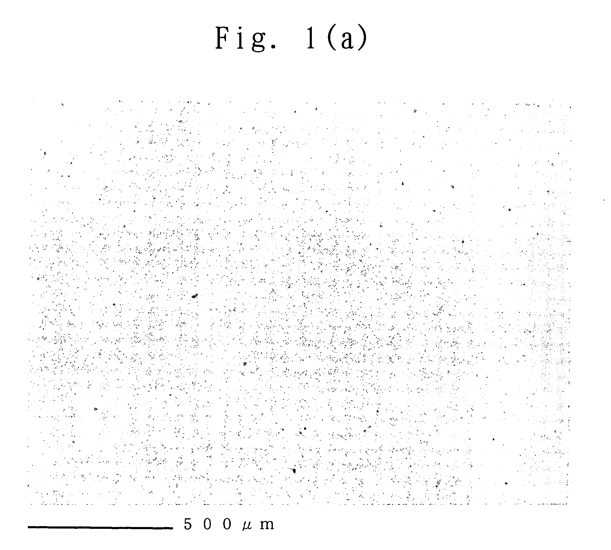
Using the casting liquid, the polymer electrolyte membrane of the present invention was produced in the same manner as in Example 2. The produced membrane was uniformly pale yellow but had high transparency. The haze value of the membrane was 3.2% (H50=3.1%). Further, a cross-sectio...


PUM

PropertyMeasurementUnit
Lengthaaaaaaaaaa
Fractionaaaaaaaaaa
Fractionaaaaaaaaaa

Abstract

A polymer electrolyte membrane comprising: (a) a fluorinated polymer electrolyte having an ion exchange group, and (b) a basic polymer, wherein, optionally, at least a part of component (a) and at least a part of component (b) are chemically bonded to each other. A method for producing the above-mentioned polymer electrolyte membrane. A membrane/electrode assembly comprising the above-mentioned polymer electrolyte membrane which is securely sandwiched between an anode and a cathode. A polymer electrolyte fuel cell comprising the membrane/electrode assembly.

Description

BACKGROUND OF THE INVENTION 1. Field of the Invention The present invention relates to a polymer electrolyte membrane for use in a polymer electrolyte fuel cell. More particularly, the present invention is concerned with a polymer electrolyte membrane comprising (a) a fluorinated polymer electrolyte having an ion exchange group, and (b) a basic polymer, wherein, optionally, at least a part of component (a) and at least a part of component (b) are chemically bonded to each other. The polymer electrolyte membrane of the present invention has excellent properties with respect to chemical stability, mechanical strength and heat stability, and exhibits high durability even when used at high temperatures. A polymer electrolyte fuel cell employing the polymer electrolyte membrane of the present invention is advantageous in that, even when the polymer electrolyte fuel cell is operated for a long time under high temperature / low humidity conditions (corresponding to an operating temperature...

Claims


Application Information

Patent Timeline
IPC IPC(8): C08J5/22C08K5/3447C08L27/12H01B1/06H01B1/12H01M4/88H01M4/92H01M8/02H01M8/10
CPCC08J5/2281H01B1/122H01M4/921H01M4/926H01M8/0291C08J2327/18H01M8/1023H01M8/103H01M8/1039H01M8/1044Y02E60/521H01M8/1004H01M8/0289C08G73/18C08J5/2218C08K5/3447C08L27/12C08L27/18C08L79/04H01B1/06H01M8/1018
Inventor MIYAKE, NAOTOWAKIZOE, MASANOBUHONDA, EIJI
Owner ASAHI KASEI CHEM CORP
Why Eureka
Try Eureka