Bond coat process for thermal barrier coating

a technology of thermal barrier coating and bond coat, which is applied in the direction of liquid fuel engine, vessel construction, marine propulsion, etc., can solve the problems of reducing the service life of gas turbine engines. , to achieve the effect of reducing labor and materials costs, reducing operating temperature, and reducing maintenance costs

Inactive Publication Date: 2005-03-17
GENERAL ELECTRIC CO
View PDF22 Cites 13 Cited by
  • Summary
  • Abstract
  • Description
  • Claims
  • Application Information

AI Technical Summary

Benefits of technology

[0013] An advantage of the present invention is that overlap between the coating on the external surface of the substrate and the coating on the internal surface of the substrate is eliminated, since aluminum is applied to both the external and internal surface of the substrate simultaneously.
[0014] Another advantage of the present invention is that the β-NiAlCrZr layer within the NiAlCrZr diffusion layer bond coat can withstand higher temperatures as compared to prior art bond coats. Also, the β-NiAlCrZr layer does not diffuse into the substrate the therefore preserves the composition of the substrate.
[0015] Another advantage of the present invention is that the method of applying the coatings of the present invention requires minimal masking of the substrate as the application of the coating of the external surface of the substrate is a two step process that does not require masking of the outer surface with alumina powder (or other maskant) when the internal surface of the substrate is aluminized.
[0016] A further advantage of the present invention is that the limited number of process steps minimizes labor and materials cost, resulting in a low cost bond coat.
[0017] Another advantage of the method of the present invention is that the outer layer of the bond coating is high in aluminum, providing an aluminum source for the formation of an alumina scale.
[0018] Other features and advantages of the present invention will be apparent from the following more detailed description of the preferred embodiment, taken in conjunction with the accompanying drawings which illustrate, by way of example, the principles of the invention.

Problems solved by technology

The operating temperature within a gas turbine engine is both thermally and chemically hostile.
Components formed from iron, nickel and cobalt-based superalloys cannot withstand long service exposures if located in certain sections of a gas turbine engine, such as the LPT and HPT sections.
However, TBC performance is limited by the thermal capability of diffusion aluminide coatings acting as bond coats.
This limitation highlights the need for cost-effective processes to apply coatings with better thermal capabilities.
In addition to the limitations of TBC performance, turbine engine components with airfoils generally use film cooling in which relatively cooler air is forced though cooling passages in the components.
In addition, the internal surfaces are not accessible to many types of coating techniques, such as those employing line-of-sight deposition processes.
The external surfaces experience hot corrosion, hot oxidation, and erosion in the combustion gas.
), a typical temperature for the internal surfaces, may lead to severe Type II corrosion on the internal surfaces.
The internal surfaces of the gas turbine components are thus subjected to environmental damage of a type substantially different from that experienced on the external surfaces.

Method used


Image

  • Bond coat process for thermal barrier coating
  • Bond coat process for thermal barrier coating
  • Bond coat process for thermal barrier coating

Examples


Embodiment Construction

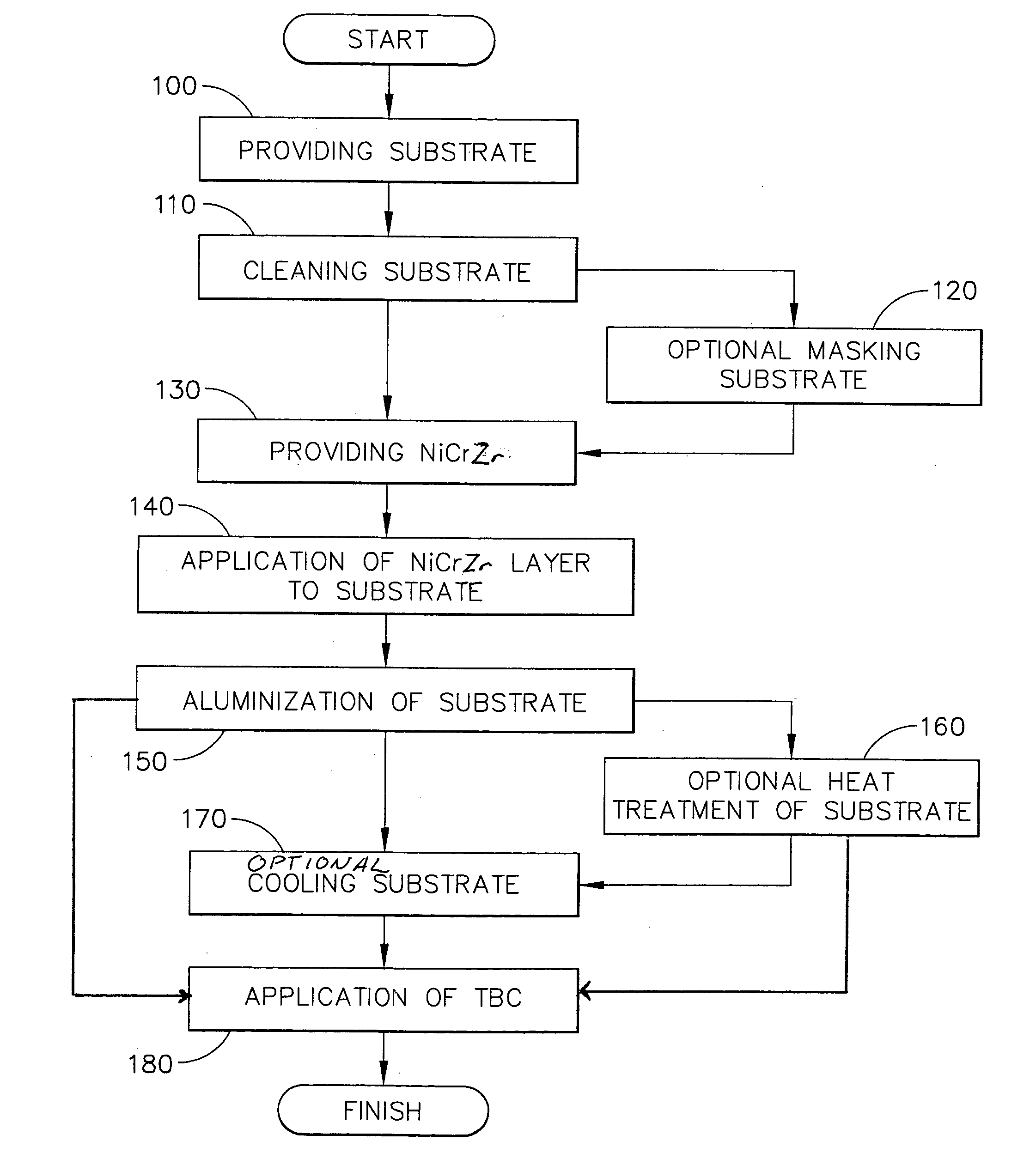
[0022] Referring now to FIG. 1 there is shown a flow chart of the method of the present invention for applying a NiAlCrZr diffusion coating to the external surface and a diffusion aluminide coating to the internal surface of a gas turbine component, at least a portion of which comprises a metallic substrate material having an internal passage therein defined by an internal surface, and an external surface. The initial step of the process 100 is the provision of a substrate having an internal passage therein defined by an internal surface, and an external surface. Optionally, some portions of the internal surface and / or external surface may be masked to prevent deposition of the subsequent NiCrZr or NiAlCrZr layer. Such masking is known to the art. In a preferred embodiment, the substrate has an internal passage therein defined by an internal surface, and an external surface. In a most preferred embodiment, the substrate is a gas turbine engine component having internal cooling passa...


PUM

PropertyMeasurementUnit
thicknessaaaaaaaaaa
thickaaaaaaaaaa
thicknessaaaaaaaaaa

Abstract

A bond coat process for thermal barrier coatings. The method includes, after cleaning and masking the external surface of the substrate, first applying a layer of NiCrZr alloy to the external surface of the substrate using a sputter coat or other suitable process. Aluminum is then applied to the substrate, using either a vapor phase aluminization (VPA) or chemical vapor deposition (CVD) process, wherein aluminum diffuses into the NiCrZr alloy layer wherein a diffusion layer is formed by the aluminum with the substrate material on the internal surface of the substrate. The coated substrate may then be subjected to a heat treatment in a protective atmosphere to further allow diffusion of the aluminide into the NiAlCrZr diffusion layer. The substantially Al outer layers of the NiAlCrZr diffusion layer, and the diffusion aluminide layer, will provide an aluminum source for the surface, which will oxidize to form a tightly adherent aluminum scale. The diffusion aluminide layer and the high Al portion of the NiAlCrZr diffusion layer will also function as a source of aluminum which will provide a reservoir to heal the alumina scale during operation.

Description

FIELD OF THE INVENTION [0001] The present invention is directed to a process for applying a bond coat and a diffusion aluminide to the surface of an aircraft engine component. More particularly, this invention relates to applying a complex multi-component bond coat formulation to the external surface and a diffusion aluminide coating to the internal surface of turbine engine components. BACKGROUND OF THE INVENTION [0002] The operating temperature within a gas turbine engine is both thermally and chemically hostile. Significant advances in high temperature capabilities have been achieved through the development of iron, nickel and cobalt-based superalloys and the use of oxidation-resistant environmental coatings capable of protecting superalloys from oxidation, hot corrosion, etc. [0003] In the compressor portion of an aircraft gas turbine engine, atmospheric air is compressed to 10-25 times atmospheric pressure, and adiabatically heated to 800°-1250° F. in the process. This heated a...

Claims


Application Information

Patent Timeline
Patent Type & Authority Applications(United States)
IPC IPC(8): F01D5/28
CPCF01D5/288F05D2300/611F05D2230/90Y02T50/67Y02T50/60
Inventor BRUCE, ROBERT WILLIAMDAS, NRIPENDRA NATHMANTKOWSKI, THOMAS EDWARD
Owner GENERAL ELECTRIC CO
Why Eureka
Try Eureka