Radiopaque markers for medical devices

a technology of radiopaque markers and medical devices, applied in the field of implantable medical devices, can solve the problems of not possessing an appreciable level of radiopacity to allow the stent to be highly visible, the stent may not be the best scaffolding device, and the radiopacity level is lower than the level of balloon expandable stents, so as to achieve sufficient radiopacity, high radiopacity, and radiopacity high

Inactive Publication Date: 2005-03-17
ABBOTT VASCULAR SOLUTIONS
View PDF46 Cites 161 Cited by
  • Summary
  • Abstract
  • Description
  • Claims
  • Application Information

AI Technical Summary

Benefits of technology

[0009] The present invention relates to an implantable medical device, such as a stent, for use or implantation in the body or a body lumen. In one aspect of the present invention, the implanted medical device includes a structural body made from a superelastic material, such as a nickel-titanium alloy, which attains a certain level of radiopacity. The structural body includes one or more marker holders which are integrally formed with the structural body. Each marker holder is designed to hold a radiopaque marker which has a level of radiopacity greater than the superelastic material. In one aspect, the radiopaque marker can be made from a nickel-titanium alloy which includes a ternary element. A ternary element is selected from a group of materials having a high level of radiopacity. For example, the ternary element can be selected from the group of elements consisting of iridium, platinum, gold, rhenium, tungsten, palladium, rhodium, tantalum, silver, ruthenium, and hafnium. In one particular embodiment of the present invention, the radiopaque marker is made from an alloy having 42.8 atomic percent nickel, 49.7 atomic percent titanium, and 7.5 atomic percent platinum. Such an alloy possesses sufficient radiopacity to create a marker system which enhances the visualization of the composite medical device during fluoroscopy or by x-ray, without affecting the physical properties of the device. Also, possible galvanic corrosion between the different alloys is eliminated altogether, or at least greatly reduced.
[0010] In another aspect of the present invention, the medical device includes a structural body having one or more marker holders adapted to receive a radiopaque marker. Each marker holder includes a pair of projecting fingers connected together at a notched region to cooperatively create a particular shaped opening. In one aspect, the opening can be V-shaped. This V-shaped opening, in turn, is adapted to receive a portion of the radiopaque marker which fits within the opening. The portion of the radiopaque marker can be V-shape as well. The V-shaped opening formed by the pair of projecting fingers creates a mounting region that allows the projecting fingers to move outwardly, if necessary, in order to receive the V-shaped portion of the radiopaque marker. In this regard, such a mounting structure allows the marker holder to easily compensate for derivations caused by an imprecise fit between the radiopaque maker and the pair of projecting fingers. Melting or heat welding at the abutment of the radiopaque marker with the projecting fingers securely affixes the components together. Such a marker system can be implemented on a number of implantable medical devices, including self-expanding stents and balloon expandable stents.
[0011] In yet another aspect of the present invention, the marker holder can take on a different configuration from the embodiment briefly described above. In this particular embodiment, the marker holder is created with a particular sized and shaped opening, such as a rectangular opening, which is adapted to receive the radiopaque marker having a comparable size and shape. In this particular embodiment, the radiopaque marker includes an inner core which is partially, or completely, encased by an outer layer. This inner core can be made from a highly radiopaque material, such as palladium, gold, or the like. The outer layer, in turn, can be formed from a material which may be easier to weld to the marker holder and may be more compatible with the marker holder to prevent galvanic corrosion. In this particular embodiment, the inner core material does not contact the marker holder so material incompatibility which may affect the ability to weld the component or promote galvanic corrosion is minimized. In one particular embodiment, the outer layer can be made with the same material used to form the marker holder. Melting or heat welding is utilized to melt a portion of the marker holder and the outer layer to meld the components together.
[0012] In still another aspect of the present invention, the marker holder can be made from a self-expanding material which utilizes a phenomenon referred to as the shape memory effect (SME) to lock the radiopaque marker in place. A shape-memory alloy (SMA) utilizes unique properties which allow the material to assume different shapes at different temperatures. Nickel-titanium alloy is a suitable SMA which could be utilized to create a marker holder which assumes a particular shape at one temperature and another shape at a different temperature. In this regard, the marker holder can be designed with an opening having a shape which normally would not be sufficiently large enough to receive the radiopaque marker, but could be deformed to another shape which readily accepts the particular size and shape of the radiopaque marker. This mounting of the marker in the opening can be performed by subjecting the marker holder to a different temperature to obtain the alternate shape. Such a marker holder could then be brought back to the first temperature which forces the marker holder into the alternative configuration, causing the marker holder to tightly grasp the marker, virtually locking it in place. The marker holder and radiopaque markers which utilize the shape memory effect as a mounting system can be adapted to a variety of shapes and sizes. Alternatively, the superelastic property of nickel-titanium also could be utilized in a similar fashion to create a similar locking system.

Problems solved by technology

Such expandable stents are often made from stainless steel alloys, such as Stainless Steel 316L or cobalt-chromium alloys, which may provide the necessary scaffolding properties needed to support the body lumen, but may not possess an appreciable level of radiopacity to allow the stent to be highly visible during fluoroscopy or by x-ray.
In such body locations, a balloon expandable stent may not be the best scaffolding device since such a stent can remain crushed if subjected to an unwanted force.
However, a distinct disadvantage with self-expanding, nickel-titanium made stents is the fact that they have an even lower level of radiopacity than balloon expandable stents made from materials such as stainless steel or cobalt-chromium alloy.
However, increasing the strut thickness usually detrimentally affects the flexibility of the stent, which is a quality necessary for ease of delivery through the patient's vasculature.
A stent having increased strut thickness also can be more difficult to deploy from the catheter delivery system.
Another complication is that radiopacity and radial force co-vary with strut thickness.
Also, nickel-titanium is somewhat difficult to machine and thick struts can exacerbate the problem.
These processes, however, can create complications such as material compatibility, galvanic corrosion, high manufacturing cost, coating adhesion or delamination, biocompatibility, loss of coating integrity following collapse and deployment of the stent, etc.
However, there are problems sometimes associated with the implementation and attachment of such radiopaque markers to the stent structure.
Such complications include difficulty in welding or bonding the marker to the stent structure due to the material incompatibility, galvanic corrosion which could be caused through the use of different materials for the markers and the stent, along with higher manufacturing costs due to the often labor intensive techniques required in order to properly attach the markers to the stent.

Method used


Image

  • Radiopaque markers for medical devices
  • Radiopaque markers for medical devices
  • Radiopaque markers for medical devices

Examples


Embodiment Construction

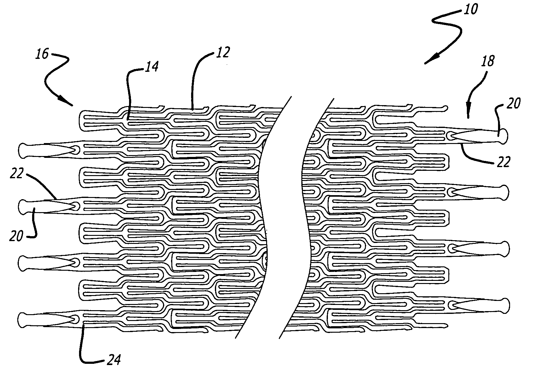
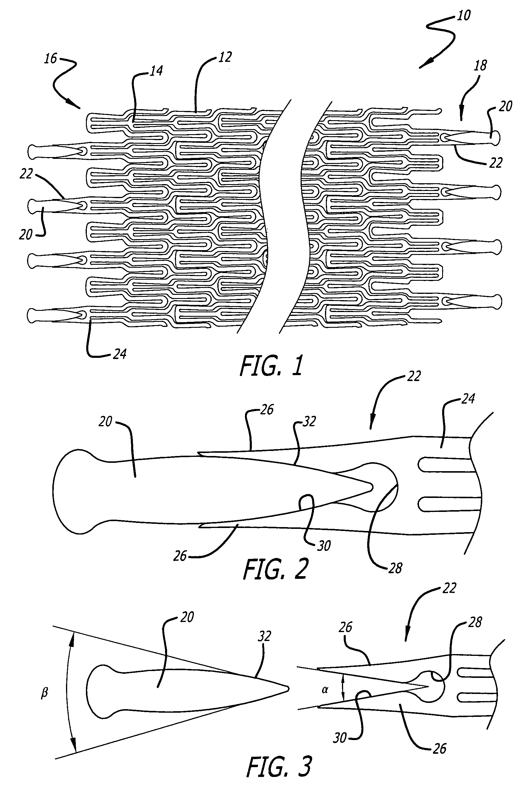
[0021] The present invention relates to radiopaque markers used to enhance the radiopacity of an implantable medical device. For the sake of illustration, the following exemplary embodiments are directed to stents, although it is understood that the present invention is applicable to other medical devices which are implantable in a body lumen as well as other parts of the body.

[0022] The stent embodiment of the present invention can have virtually any configuration that is compatible with the body lumen in which they are implanted. The stent should preferably be configured so that there is a substantial amount of open area. The stent should also be configured so that dissections or flaps in the body lumen wall are covered and tacked up by the stent.

[0023] Referring now to FIG. 1, in one particular embodiment of the present invention, a stent 10 is formed partially or completely from an alloy such as nitinol (NiTi), which has superelastic (SE) characteristics. The strut pattern of ...


PUM


Abstract

An implantable medical device includes a structural body made from a superelastic material and includes one or more marker holders integrally formed on the structural body. Each marker holder is designed to hold a radiopaque marker which has a level of radiopacity greater than the superelastic material. The radiopaque marker can be made from a nickel-titanium alloy which includes a ternary element. The ternary element can be selected from the group of elements consisting of iridium, platinum, gold, rhenium, tungsten, palladium, rhodium, tantalum, silver, ruthenium, and hafnium. In one form, the marker holder includes a pair of projecting fingers connected together at a notched region to cooperatively create a particular-shaped opening. This opening, in turn, is adapted to receive a similarly shaped portion formed on the radiopaque marker. In one form, the radiopaque marker includes an inner core which is partially, or completely, encased by an outer layer. This inner core can be made from a highly radiopaque material while the outer layer is formed from a material that is easier to weld to the marker.

Description

BACKGROUND OF THE INVENTION [0001] The present invention generally relates to implantable medical devices, such as endoprosthesic devices generally known as stents, and more particularly, to radiopaque markers which can be used with such medical devices to increase the visualization of the implanted medical device during fluoroscopy or by x-ray. [0002] Stents are typically implanted in a body lumen, such as carotid arteries, coronary arteries, peripheral arteries, veins, or other vessels to maintain the patency of the lumen. These devices are frequently used in the treatment of atherosclerotic stenosis in blood vessels especially after percutaneous transluminal angioplasty (PTA) or percutaneous transluminal coronary angioplasty (PTCA) procedures with the intent to reduce the likelihood of restenosis of a vessel. Stents also are used to support a body lumen, tack-up a flap or dissection in a vessel, or in general where the lumen is weak to add support. Stents, or stent-like devices, ...

Claims


Application Information

Patent Timeline
Patent Type & Authority Applications(United States)
IPC IPC(8): A61F2/00A61F2/06A61F2/90
CPCA61F2/91A61F2/915A61F2250/0098A61F2002/91575A61F2002/91591A61F2002/91533
Inventor MACKIEWICZ, DAVID A.FITZGERALD, KEIFANUKHIN, BORIS
Owner ABBOTT VASCULAR SOLUTIONS
Why Eureka
Try Eureka