
Fuel cell gas separator plate

a technology of gas separator plate and fuel cell, which is applied in the field of fuel cells to achieve the effects of enhancing electrical contacts, reducing loss of silver-glass composite, and reducing loss of glass

Inactive Publication Date: 2005-03-24
CERAMIC FUEL CELL LTD
View PDF25 Cites 9 Cited by
  • Summary
  • Abstract
  • Description
  • Claims
  • Application Information

AI Technical Summary

Benefits of technology

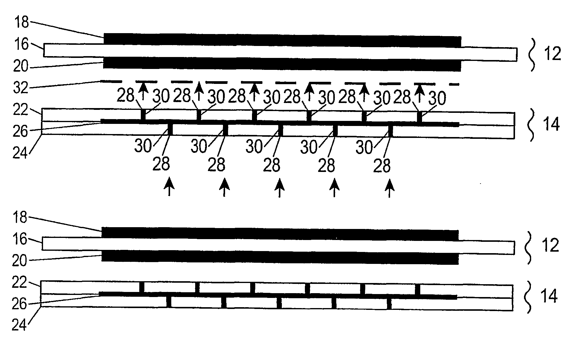
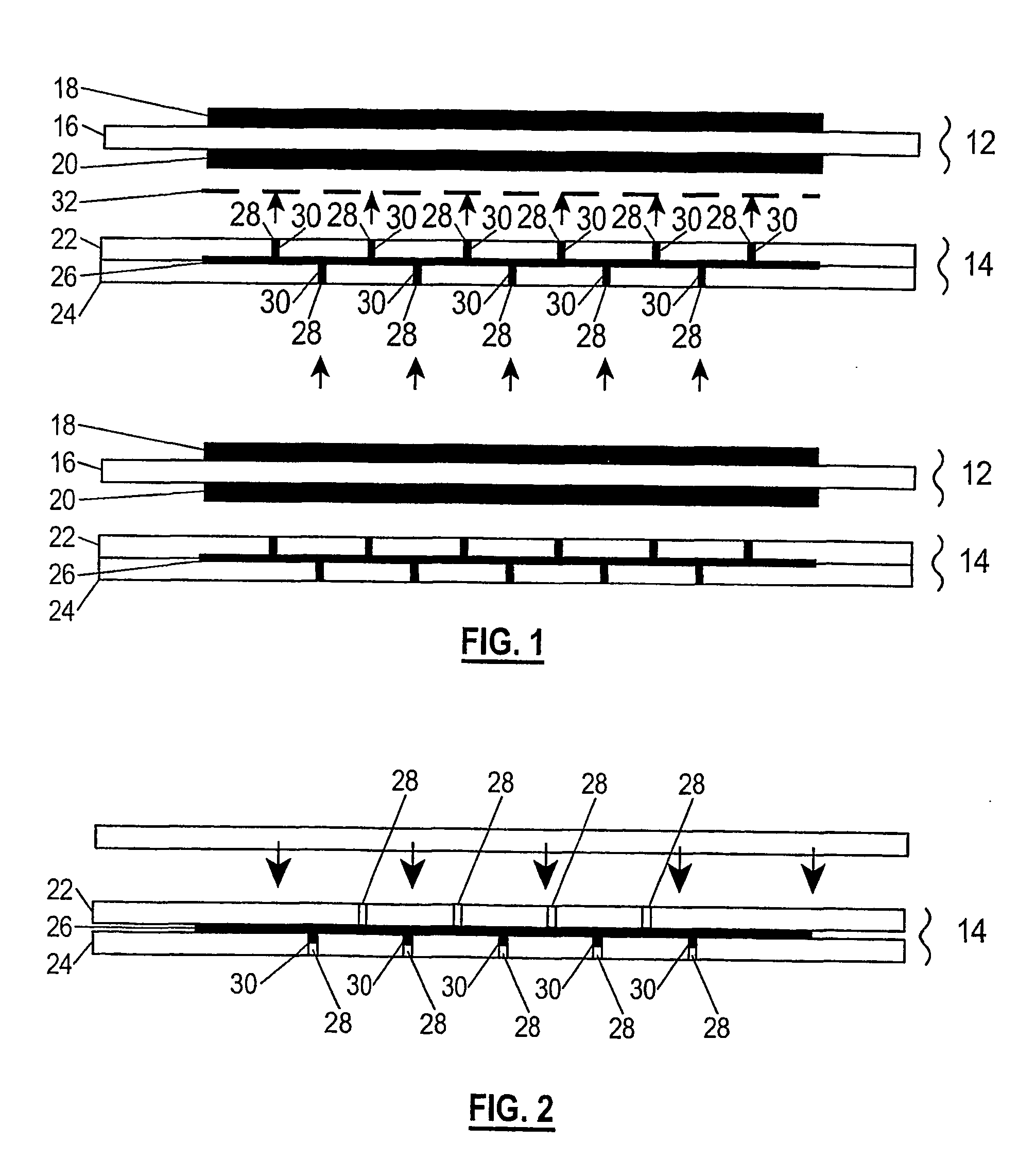
[0016] By this aspect of the present invention, the advantage of separating the desired level of electrical conductivity of the gas separator from the material of the separator body is achieved by the use of silver in the electrically conductive paths through the separator body, and the risk of leakage of gases through the gas separator is alleviated by the use of glass in the electrically conductive paths. The glass may soften at the operating temperature of the fuel cell and, if necessary, can flow with expansion and contraction of the separator body as the separator is subjected to thermal cycling. The ductility of the silver facilitates this. The silver-glass composite may effectively be in the form of pure silver or a silver-based material in a glass matrix.
[0045] For convenience, such perforations preferably extend substantially perpendicularly through the thickness of the separator body. However, this is not essential and it may be advantageous for the paths of electrically conductive material to be inclined to the perpendicular. Each path at the anode-side of the separator body may be offset relative to a connected path at the cathode-side to further alleviate the risk of leakage of gases through the separator, and / or the separator body may be formed as two or more layers separated by a layer or layers of electrically conductive material that may be the same as or different to the electrically conductive material in the paths through the separator body, as described above.

Problems solved by technology

About 10 wt % glass is believed to be the lower limit to provide adequate sealing advantages in the separator body, while at a level above about 40 wt % glass there may be insufficient silver in the composite to provide the desired level of electrical conductivity.

Method used


Image

  • Fuel cell gas separator plate
  • Fuel cell gas separator plate
  • Fuel cell gas separator plate

Examples


Embodiment Construction

[0062] Referring to FIG. 1 there is shown an array 10 of alternating fuel cells 12 and gas separator plates 14 in accordance with the invention. The fuel cells 12 are planar and comprise a solid oxide electrolyte support layer 16 with an anode layer 18 on one side and a cathode layer 20 on the other side. The electrolyte is preferably yttria-stabilized zirconia such as 3Y, 8Y or 10Y. The anode is preferably a nickel-zirconia cermet and the cathode is preferably a conductive perovskite such as lanthanum strontium manganate. Such solid oxide fuel cells are well known and will not be described further.

[0063] Each gas separator plate 14 has a three-layer sandwich structure with first and second outer layers 22 and 24, and a third intermediate layer 26.

[0064] The first and second layers are conveniently formed of a zirconia to substantially match the CTE of the electrolyte support layer 16 of the fuel cells 12. The zirconia may be yttria-stabilized, but could be, for example, an alumin...


PUM

PropertyMeasurementUnit
thicknessaaaaaaaaaa
thicknessaaaaaaaaaa
temperaturesaaaaaaaaaa

Abstract

A fuel cell gas separator (212) for use between two solid oxide fuel cells (210) and having a separator body with an anode-facing side and a cathode-facing side and with paths (234) of electrically conductive material therethrough in an electrode-contacting zone (236). In a first aspect, the electrically conductive material comprises a silver-glass composite, preferably containing 15 to 30 wt % glass. In this aspect the material of the separator body is preferably zirconia and the silver is commercially pure, a silver mixture or a silver alloy. In another aspect, the material of the separator body is zirconia, the electrically conductive material comprises silver or a silver-based material, a coating of nickel is formed on the electrode-contacting zone (236) on the anode-facing side preferably with an undercoating of Ag, and a coating of Ag—Sn alloy is formed on the electrode-contacting zone (236) on the cathode side.

Description

FIELD OF THE INVENTION [0001] The present invention relates to fuel cells and is particularly concerned with gas separators between adjacent solid oxide fuel cells. BACKGROUND OF THE INVENTION [0002] The purpose of a gas separator in a fuel cell assembly is to keep the oxygen containing gas supplied to the cathode side of one fuel cell separate from the fuel gas supplied to the anode side of an adjacent fuel cell, and to conduct heat generated in the fuel cells away from the fuel cells. The gas separator may also conduct electricity generated in the fuel cells between or away from the fuel cells. Although it has been proposed that this function may alternatively be performed by a separate member between each fuel cell and the gas separator, much development work has been carried out on electrically conductive gas separators. [0003] Sophisticated ceramics for use in gas separators for solid oxide fuel cells have been developed which are electrically conductive, but these suffer from ...

Claims


Application Information

Patent Timeline
Patent Type & Authority Applications(United States)
IPC IPC(8): H01M4/86B22F3/00C03C8/18C03C8/24H01M8/02H01M8/12H01M8/24
CPCB22F3/00Y02E60/525C03C8/24H01M8/0204H01M8/0206H01M8/0215H01M8/0217H01M8/0226H01M8/0228H01M8/0247H01M8/0256H01M8/0271H01M8/0282H01M8/2425H01M8/2475H01M2008/1293Y02E60/50C03C8/18H01M8/2483H01M8/2432H01M8/0258H01M8/02
Inventor RODRIGO, PULAHINGA DON DAYANANDAARULIAH, SATHIA KAMARASIGHE, SUDATHHUGHAN, ROBERT RANDOLPHLAWRENCE, JEREMY CARLBARKER, JARROD DAVID
Owner CERAMIC FUEL CELL LTD
Learn More