Differactive micro-structure color wavelength division device

a color wavelength division and diffractive micro-structure technology, applied in the direction of picture reproducers, picture reproducers using projection devices, instruments, etc., can solve the problems of large portion of wavelength blockage, adsorption or loss of remaining spectral wavelengths, waste of light sources, etc., to enhance the optical operation efficiency of liquid crystal displays and enhance the aspect ratio

Inactive Publication Date: 2005-03-24
IND TECH RES INST
View PDF3 Cites 33 Cited by
  • Summary
  • Abstract
  • Description
  • Claims
  • Application Information

AI Technical Summary

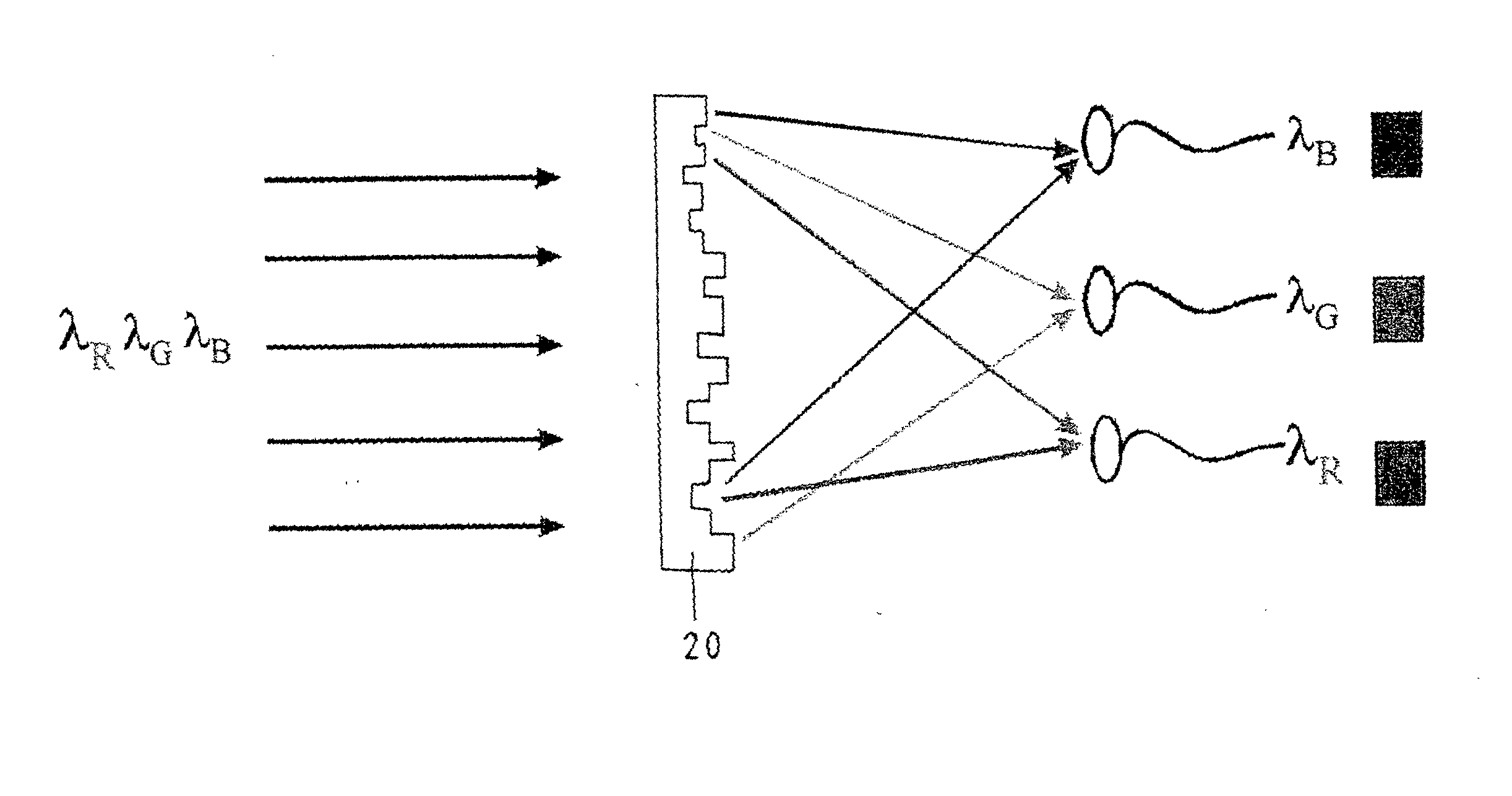
Benefits of technology

[0006] The primary objective of the present invention is to provide a diffractive micro-structure color wavelength disvision device, which employs the diffraction theory and the binary optics operation in conjunction with the phase iteration method to calculate a complex two-dimensional surface phase micro-structure color wavelength division device. This geometric micro-structure color wavelength optical element has a multiwavelenght modulation function capable of wavelength division and focus. The device is used in the liquid crystal display for splitting the light source. Each spectrum region of wavelengths is focused on the corresponding TFT subpixel, thereby resulting in enhancement of the aspect ratio at such time when the light coupling takes place. In the meantime, the adsorption of light energy by the color filter is minimized so as to enhance the optical operational efficiency of the liquid crystal display.
[0007] It is another objective of the present invention to provide a diffractive micro-structure color wavelength division device comprising a color wavelength division device capable of wavelength division and wavelength focus, thereby resulting in elimination of lens array as well as light collimating procedures. The present invention is simple in construction such that the production cost of the module is substantially reduced, and that the system can be miniaturized.
[0008] It is still another objective of the present invention to provide a diffractive micro-structure color wavelength division device comprising a color wavelength division device which is planarized, small in area, and excellent in light transparency. The present invention can be used as a single unit or array to form the liquid crystal module of a liquid crystal display.
[0009] It is still another objective of the present invention to provide a diffractive microstructure color wavelength division device comprising a color wavelength division element which has a combined effect of the conventional color filter and the lens array. When the present invention is used in a color CCD system, the system is simplified in construction in that the number of component parts is reduced, and that the optical efficiency of the system is enhanced, and further that the aspect ratio of the system is improved.

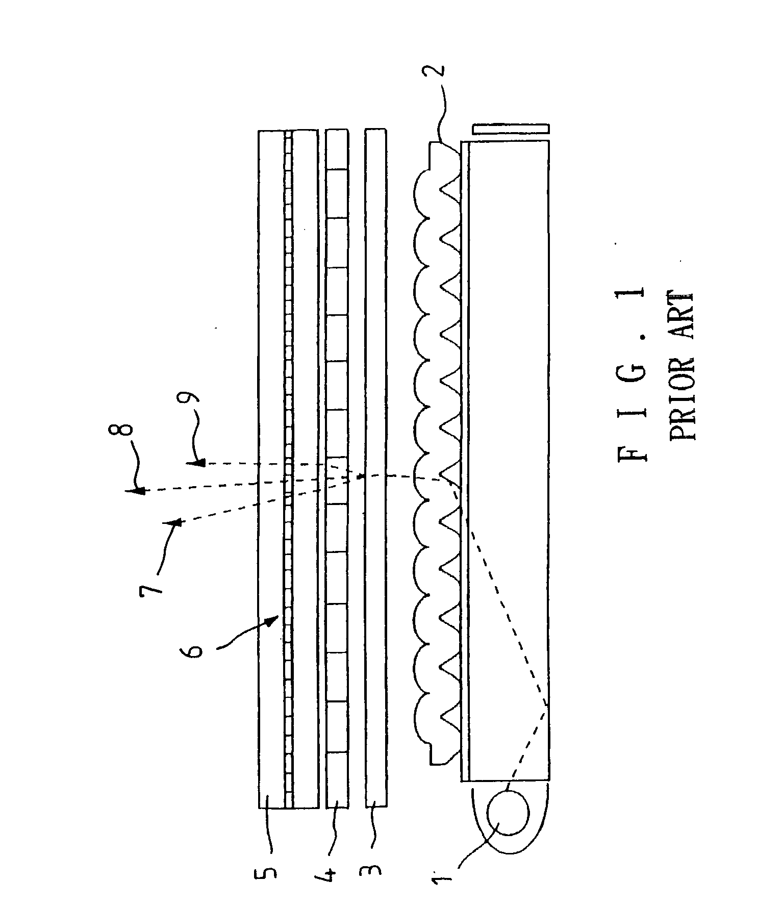
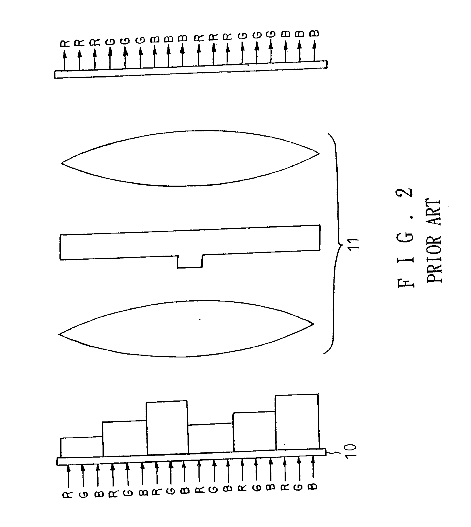
Problems solved by technology

However, when the backlight source is introduced into the TFT pixel, a large portion of the wavelength is blocked by a circuit portion of the TFT pixel.
In the wake of the passage of the wavelength through the TFT pixel, only the corresponding red, blue, or green spectrum region of wavelengths is allowed to pass through a corresponding filter, thereby resulting in adsorption or loss of the remaining spectral wavelengths.
As a result, the light source is wasted.
Meanwhile, the operational efficiency of the display system is thus undermined.
Such a mechanism as described above calls for a cooperation of the light dispersive element 3 and the focusing element 4, thereby resulting in assembly complication as well as an increase in module cost.
Such a system as described above involves a complicated problem of assembly and collimation.
The system is not cost-effective and can not be miniaturized.
The system is therefore complicated in construction and not cost-effective.

Method used


Image

  • Differactive micro-structure color wavelength division device
  • Differactive micro-structure color wavelength division device
  • Differactive micro-structure color wavelength division device

Examples


Embodiment Construction

[0025] The phase equation that is needed to calculate the diffractive microstructure optical element of the present invention is attained through the theoretical calculation of binary optics and diffraction optics. The surface structure of the element is then solved by the phase iteration method. The loops of iterative process is expressed as follows: ϕ2⁢k⁢ ⁢α=arg⁢{∑j=1N1⁢G^k⁢ ⁢j⁢ ⁢α⁢ρ1⁢j⁢ ⁢α⁢ⅇⅈ(2⁢π⁢ ⁢h1⁢j⁡(ns⁢ ⁢α-1)λα)∑j=1N1⁢G^k⁢ ⁢j⁢ ⁢α⁢ρ1⁢j⁢ ⁢α⁢ⅇⅈ(2⁢π⁢ ⁢h1⁢j⁡(ns⁢ ⁢α-1)λα)}⁢⁢ϕ1⁢j=Qj*Qj⁢⁢Qj=∑α=1m⁢2⁢π⁡(ns⁢ ⁢α-1)λα⁢{∑i=1≠jN1⁢ρ1⁢i⁢ ⁢α⁡(G+^,G^)ij⁢ ⁢α⁢ⅇⅈ(2⁢π⁢ ⁢h1⁢j⁡(ns⁢ ⁢α-1)⁢h1⁢iλα)-∑k=1N2⁢ρ2⁢k⁢ ⁢α⁢G^kj⁢ ⁢α⁢ⅇ-ⅈϕ2⁢k⁢ ⁢α]⁢ρ1⁢j⁢ ⁢α×ⅇⅈ⁢2⁢π⁢ ⁢h1⁢j⁢(n0-1)λ0⁡[λ0⁡(ns⁢ ⁢α-1)λα⁡(n0-1)-1]}λ0=∑α=1m⁢λαm⁢ ⁢n0=∑α=1m⁢n⁡(λα)m

[0026] in which φ1 stands for phase of element; φ2 phase of optical field.

[0027] On the basis of phase of element, the surface structure of the element is obtained by a program computation, as shown in FIG. 4. FIG. 4 shows a 3-dimensional micro-structure of two wavelengths capable...


PUM

PropertyMeasurementUnit
wavelengthsaaaaaaaaaa
microstructureaaaaaaaaaa
phase iteration algorithmaaaaaaaaaa

Abstract

A diffractive micro-structure color wavelength division device makes use of diffraction theory, binary optics theory, and operation of phase iteration algorithm to its complex two-dimensional surface phase micro-structure. The color wavelength division device has a multi-wavelength modulation function and is capable of wavelength division and focus, thereby resulting in structural simplification and enhancement of light utilized efficiency of a color image system.

Description

FIELD OF THE INVENTION [0001] The present invention relates generally to a two-dimensional surface phase micro-structure optical element for use in a color image display system. The diffractive micro-structure color wavelength division device which is capable of multi-wavelength division and focus and is intended to simplify the feature of component parts of a color image display system and to enhance the optical efficiency of the color image display system. BACKGROUND OF THE INVENTION [0002] In light of economic and technical advantages of the liquid crystal display over the CRT display, the liquid crystal display is widely used in the display system to attain exhibition of a color image by means of the chemical color filter. The liquid crystal panel contains three TFT subpixels of R.G.B, which are respectively provided with a filter permeable to only red, blue, and green spectra. However, when the backlight source is introduced into the TFT pixel, a large portion of the wavelength...

Claims


Application Information

Patent Timeline
Patent Type & Authority Applications(United States)
IPC IPC(8): G02B5/18G02F1/13G02F1/1335G02F1/13357H04N9/04H04N9/31
CPCG02B5/1838G02F1/133526H04N9/3197H04N9/045H04N9/3108G02F1/133621H04N23/84
Inventor YAU, PO-HUNGPAO, YU-NANYANG, JAUH-JUNG
Owner IND TECH RES INST
Why Eureka
Try Eureka