Electrolysis device for treating a reservoir of water

Inactive Publication Date: 2005-03-31
THE PROCTER & GAMBNE CO
View PDF19 Cites 57 Cited by
  • Summary
  • Abstract
  • Description
  • Claims
  • Application Information

AI Technical Summary

Benefits of technology

A preferred method continuously treats the reservoir of electrolytic solution with the electrolysis device, thereby preventing a re-contamination of the reservoir. A preferred method treats the reservoir solution by passing at least a portion of the reservoir solution to the electrolysis device, electrolyzing the portion of reservoir water in an electrolysis cell of the electrolysis device, thereby forming an effluent of electrolyzed water comprising a quantity of mixed oxidant material, discharging the effluent into the reservoir of wat

Problems solved by technology

Nevertheless, these supplies are not completely effective at killing all of the bacteria and other pathogens, and can become contaminated with bacteria and other pathogens as a result of faulty treatment operations.
Despite modern water purification means, the general population is at risk, and in particular infants and persons with compromised immune systems are at considerable risk.
Even the freshest of these water sources has some level of harmful bacteria and other pathogens.
Very often these water sources can be highly polluted and can contain extremely high level of harmful microorganisms and pathogens.
There are deadly consequences associated with exposure to contaminated water, caused by increasing population densities, increasingly scarce water resources, and often no community water treatment utilities.
It is common for sources of drinking water to be in close proximity to human and animal waste, such that microbiological

Method used


Image

  • Electrolysis device for treating a reservoir of water
  • Electrolysis device for treating a reservoir of water
  • Electrolysis device for treating a reservoir of water

Examples


Example

Embodiment I

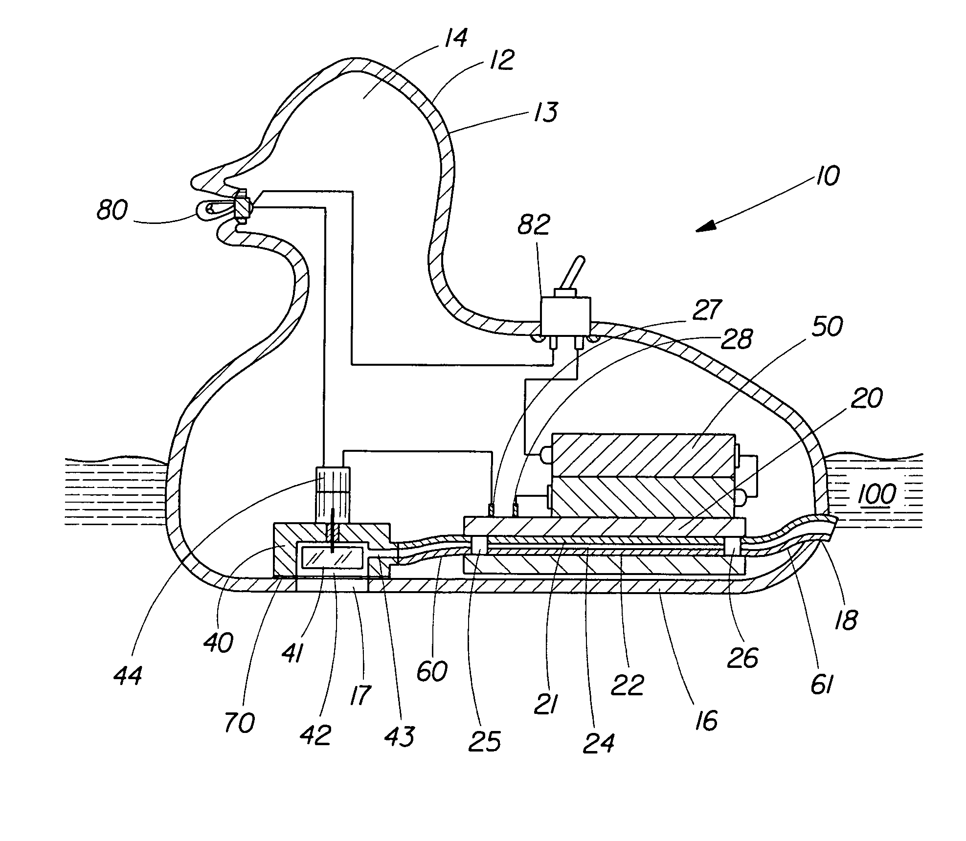
An example of a self-contained, self-propelled electrolysis device is shown in cross section in FIG. 4. The duck electrolysis device 10 has a buoyant body 12 made into the form of a duck. The body has a substantially continuous outer surface 13 and a hollow interior 14. The body is molded from a rubberized PVC plastic. Within the interior of the body, mounted to the base 16 is an electrically-driven motor 44 (model RE260, LMP Inc., Jersey City, N.J.) that drives a pump 40 having impeller 41 (model IMPELR-S, Swampworks Mfg., Springfield, Mo.). The inlet 42 to the pump is positioned directly against an inlet opening 17 in the base 16 of the body to provide fluid communication between the reservoir 100 of water and the inlet 42 to the pump. The periphery of the pump outboard of the pump inlet is sealed to the base 16 with a water-proof adhesive 70 to prevent any leakage of reservoir water into the body of the device. The discharge 43 of the pump is connected via ¼ inch T...

Example

Embodiment II

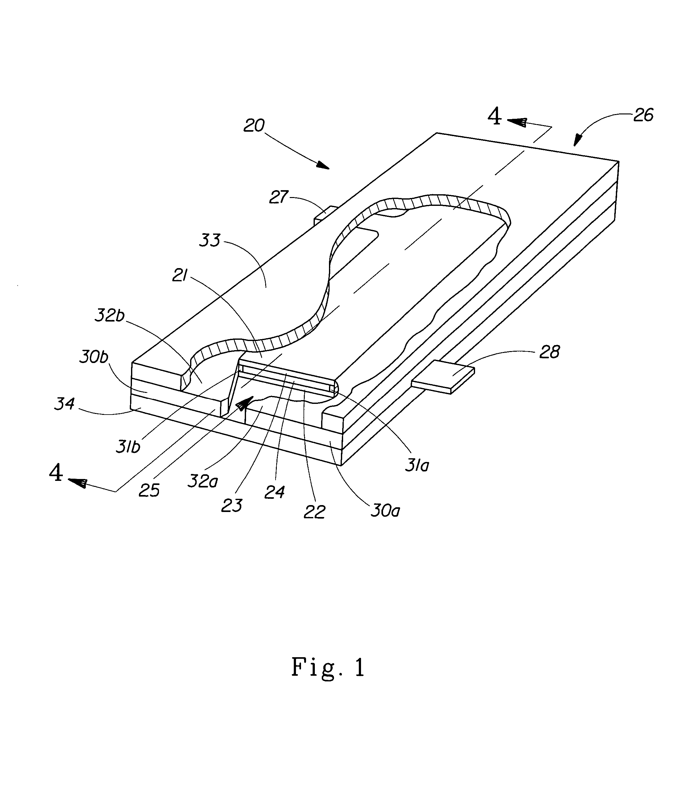
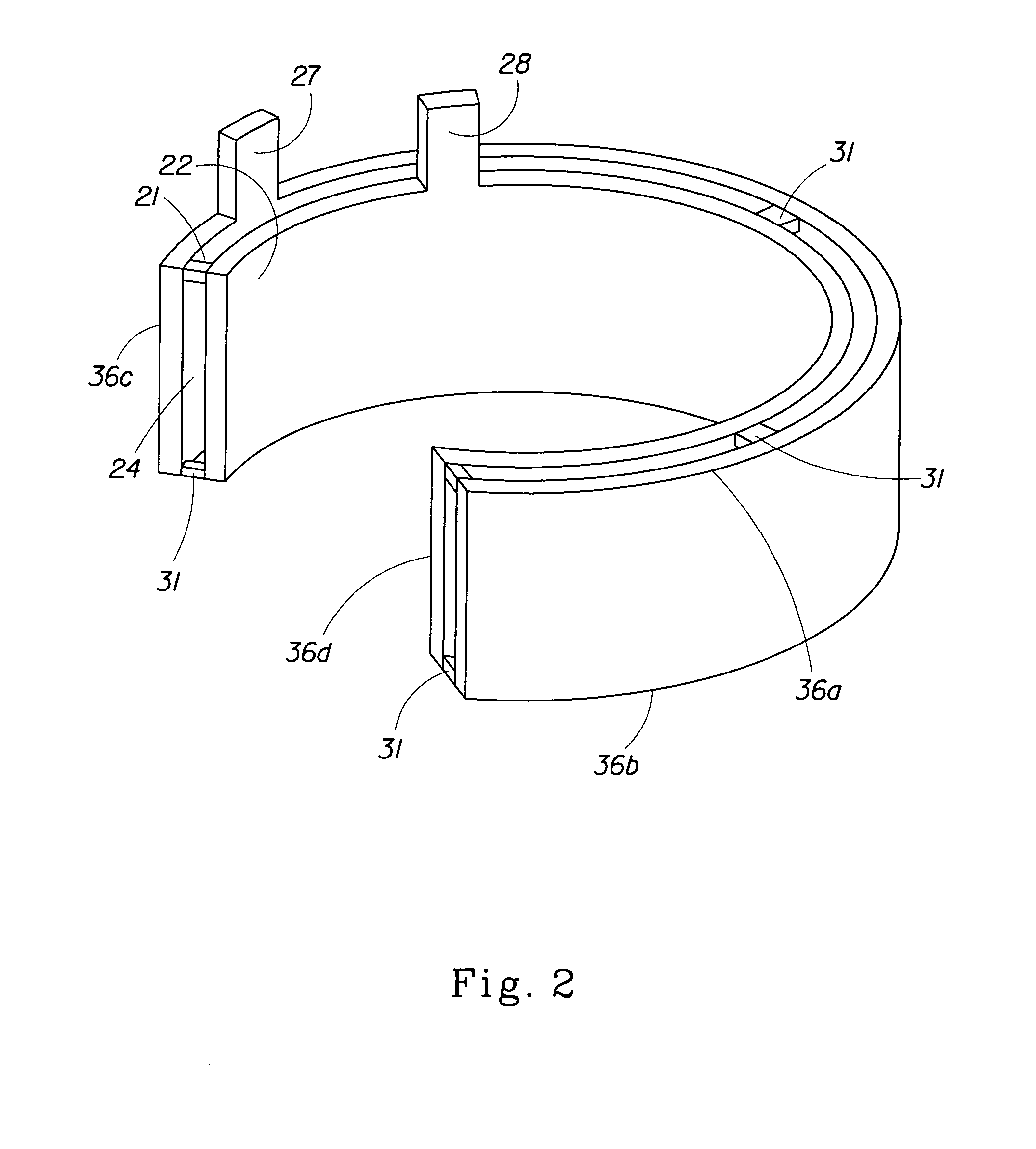
An example of a self-powered self-contained electrolysis device with a close-spaced gap between the electrodes is shown in partial cross section in FIG. 5. FIG. 5 shows an electrolysis device 10 having a self-contained body 12 made into the form of a boat. The body is made from PVC plastic. Mounted on the exterior of the base 16 of the self-contained body is an electrolysis cell 20 of the type shown in FIG. 3 (shown in FIG. 5 in cross section taken through line 5-5 of FIG. 3), having a planar anode plate 21 and a confronting planar cathode plate 22. The anode plate is made of titanium with an iridium oxide coating (0.4 microns thick) and measuring 7.2 cm long and 2.7 cm wide. The cathode plate is made of stainless steel (1.45 mm thick), having the same length and width dimensions as the anode. The cathode plate have a constant gap spacing of 0.40 mm between the two electrodes. An electrical current supply 50 consisting of two “AA” alkaline batteries (each 1.5V) is po...


PUM


Abstract

A self-powered self-contained electrolysis device, for placement into a reservoir of a contaminated electrolytic solution, such as water, containing halide ion, such as chloride ion, to electrolyze the water, thereby disinfecting or sterilizing the contaminated reservoir of water. Contaminated reservoirs of water can be water containers filled with river water and other outdoor sources, or can be contaminated municipal water held in kitchen containers, cooling systems, water tanks, cisterns, etc. The self-contained body allows the electrolysis device to float on or remain self-contained in the reservoir water. Preferred devices are small and portable, and comprise reliably productive electrolysis cells that are powered by batteries. A means for propulsion of the device can also be provided, and is preferably a pump that pumps the water through the electrolysis cell.

Description

FIELD OF THE INVENTION This invention relates to an electrolysis device having an electrolysis cell for treating a reservoir of water or other electrolyte solution. BACKGROUND OF THE INVENTION The worldwide population uses water daily for drinking, cooking, bathing, cleaning, and other personal uses. In many countries, the supply of water is made relatively safe for consumption or for contact with the body through municipal water treatments. Such municipal treatment usually uses chemicals, such as chlorine or ozone, to treat the water to destroy harmful microorganisms in the water. Nevertheless, these supplies are not completely effective at killing all of the bacteria and other pathogens, and can become contaminated with bacteria and other pathogens as a result of faulty treatment operations. In a variety of circumstances, these contaminants must be removed or neutralized before the water can be used. For example, in many medical applications and in the manufacture of certain ele...

Claims


Application Information

Patent Timeline
IPC IPC(8): C02F1/461C02F1/467
CPCC02F1/46104C02F1/4674C02F2001/46133C02F2001/46152C02F2001/46161C02F2101/103E04H4/1281C02F2201/008C02F2201/009C02F2201/4611C02F2201/46165C02F2201/4618C02F2103/42Y02W10/37Y02A20/212C02F1/461
Inventor TREMBLAY, MARIO ELMEN
Owner THE PROCTER & GAMBNE CO
Why Eureka
Try Eureka