Lithographic printing plate precursor and lithographic printing method
a technology of lithographic printing plate and precursor, which is applied in thermography, instruments, photosensitive materials, etc., can solve the problems of insufficient press life, insufficient on-press development, and insufficient compatibility with fine line reproducibility and press li
- Summary
- Abstract
- Description
- Claims
- Application Information
AI Technical Summary
Benefits of technology
Problems solved by technology
Method used
Image
Examples
example 1
(1) Manufacture of Support:
For removing the rolling oil of the surface, an aluminum sheet having a thickness of 0.3 mm (material 1050) was subjected to degreasing treatment with a 10% by weight sodium alminate aqueous solution at 50° C. for 30 seconds, and then the aluminum surface was subjected to brush-graining with three nylon brushes planted with hairs having a hair diameter of 0.3 mm and a suspension of pumice stone and water of a median diameter of 25 μm (the specific gravity: 1.1 g / cm3), and the surface of the sheet was thoroughly washed with water. The sheet was immersed in a 25% by weight sodium hydroxide aqueous solution at 45° C. for 9 seconds for etching, and washed with water. After water washing, the sheet was further immersed in a 20% by weight nitric acid aqueous solution followed by washing with water. The etched amount of the surface by graining was about 3 g / m2.
Electrochemical surface roughening treatment was performed continuously by alternating voltage of 6...
example 2
The image-recording layer coating solution (2) having the composition shown below was coated on the support obtained in Example 1 with bar coating, dried at 100° C. for 60 seconds in an oven, whereby an image-recording layer having a dry coating amount of 1.0 g / m2 was formed. The overcoat layer coating solution (1) in Example 1 was coated on the above-formed image-recording layer in a layer thickness of 0.5 g / m2 with wire bar coating, and dried at 70° C. for 60 seconds in the same manner, whereby lithographic printing plate precursor 2 was obtained.
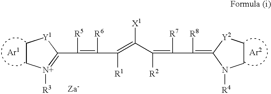
Image-forming layer coating solution (2):The following infrared absorber (2)0.05gThe above polymerization initiator (1)0.2gThe following binder polymer (1)0.5g(average molecular weight: 80,000)Polymerizable compound1.0gIsocyanuric acid EO-modified triacrylate(NK ester M-315, manufactured bySHIN-NAKAMURA CHEMICAL CO., LTD.)Naphthalene sulfonate of Victoria Pure Blue0.02gThe above fluorine surfactant (1)0.1gMethyl ethyl ketone18.0gInfrar...
example 3
Lithographic printing plate precursor 3 was obtained in the same manner as in Example 1 except for changing the mica dispersion to the following mica dispersion (2).
Preparation of Mica Dispersion (2):
Synthetic mica (12 g) (Suzulight 40H, manufactured by MRI INTERNATIONAL INC.) was added to 188 g of water containing 2 g of sodium dodecylsulfate, and dispersed with a homogenizer at 10,000 rpm for 30 minutes, and 200 g of a 5.6% by weight gelatin aqueous solution was further added thereto, whereby mica dispersion (2) was obtained.
PUM
| Property | Measurement | Unit |
|---|---|---|
| Wavelength | aaaaa | aaaaa |
| Area | aaaaa | aaaaa |
Abstract
Description
Claims
Application Information
 - R&D
- Intellectual Property
- Life Sciences
- Materials
- Tech Scout
- Unparalleled Data Quality
- Higher Quality Content
- 60% Fewer Hallucinations
Browse by: Latest US Patents, China's latest patents, Technical Efficacy Thesaurus, Application Domain, Technology Topic, Popular Technical Reports.
© 2025 PatSnap. All rights reserved.Legal|Privacy policy|Modern Slavery Act Transparency Statement|Sitemap|About US| Contact US: help@patsnap.com


