Reflection mirror apparatus, exposure apparatus and device manufacturing method

Inactive Publication Date: 2005-04-07
CANON KK
View PDF18 Cites 30 Cited by
  • Summary
  • Abstract
  • Description
  • Claims
  • Application Information

AI Technical Summary

Benefits of technology

[0008] According to one aspect of the present invention, a reflection mirror apparatus in an exposure apparatus, constructing a reflection optical system to guide exposure light by reflection is provided, which comprises: a mirror having a reflection surface that reflects the exposure l

Problems solved by technology

As the extreme ultraviolet light is greatly attenuated when it passes through an object, an optical control system using an optical lens cannot be employed.
Accordingly, as apparent from the above description, the extremely high accuracy of surface form of about 1 nm cannot be ensured due to displacement of mirror reflection surface by heat.
In the case of the projection optical system, the above degradation of accuracy of surface form in the mirror causes degradation of image formation performance and illumination on the

Method used


Image

  • Reflection mirror apparatus, exposure apparatus and device manufacturing method
  • Reflection mirror apparatus, exposure apparatus and device manufacturing method
  • Reflection mirror apparatus, exposure apparatus and device manufacturing method

Examples


first embodiment

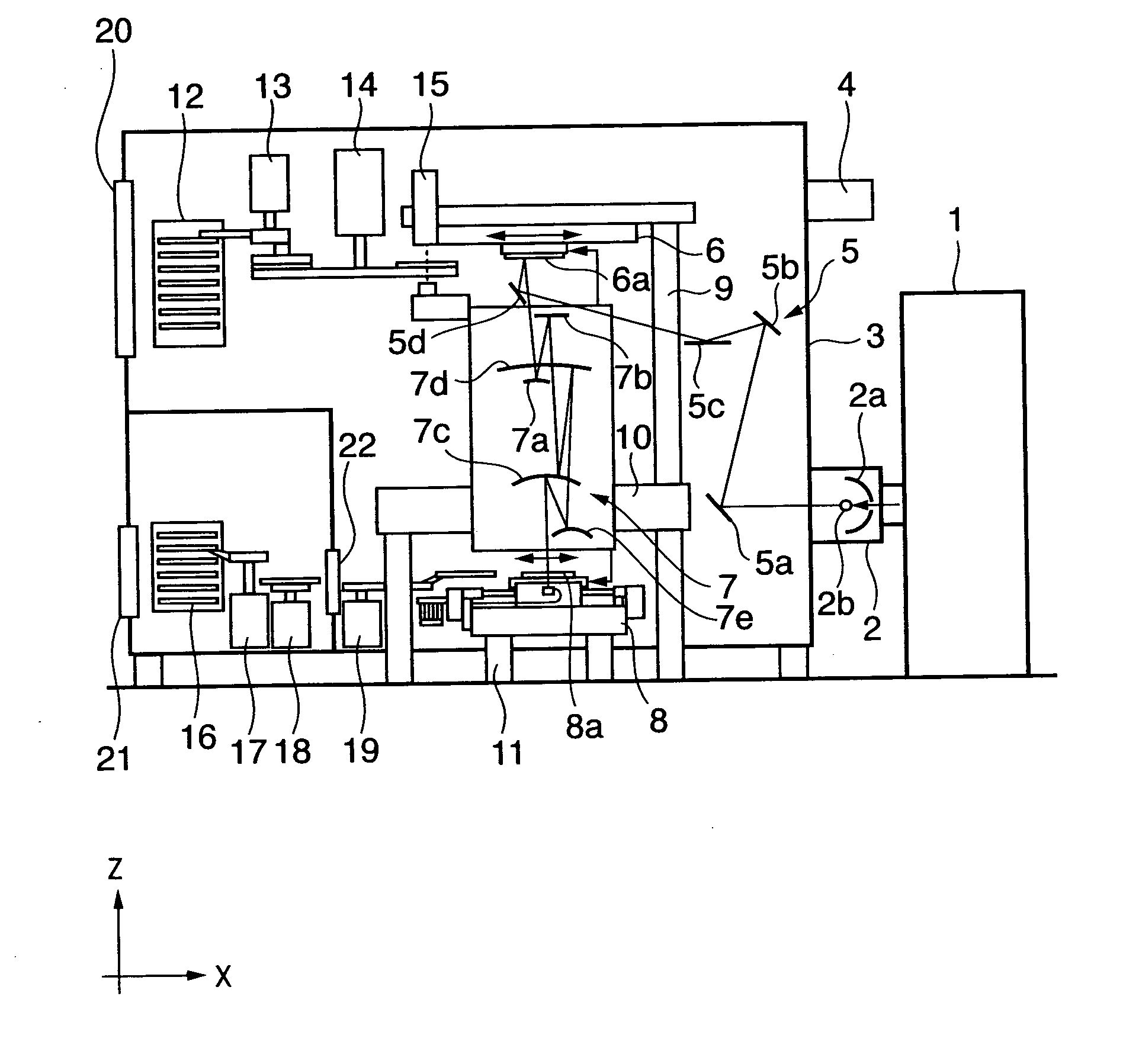
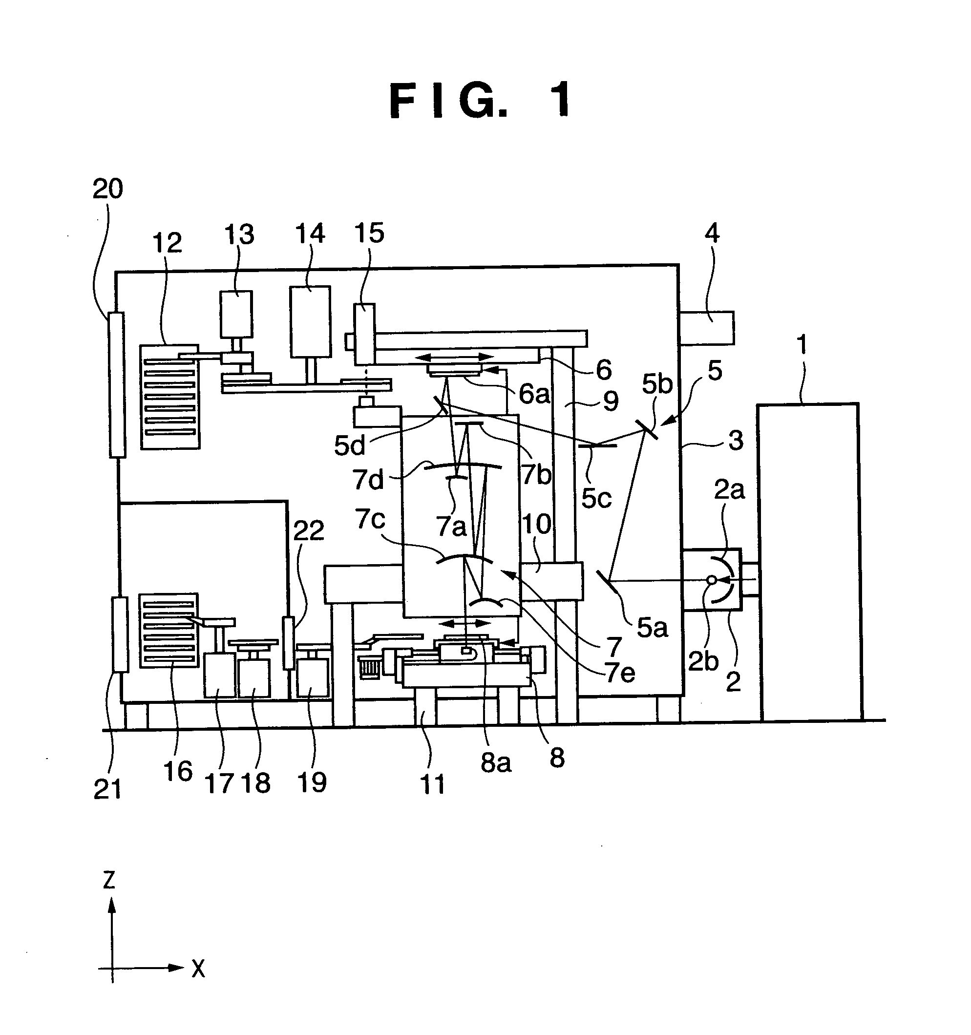
[0027]FIG. 1 is a schematic cross-sectional view showing the structure of an exposure apparatus according to the present invention. In FIG. 1, reference numeral 1 denotes an excitation laser. The laser is emitted toward a point where a light source material is gasified, liquefied or spray-gasified, as a light emission point of light source, for plasma excitation of atoms of the light source material, thereby extreme ultraviolet light is emitted. In the present embodiment, a YAG solid laser or the like is used as the excitation laser.

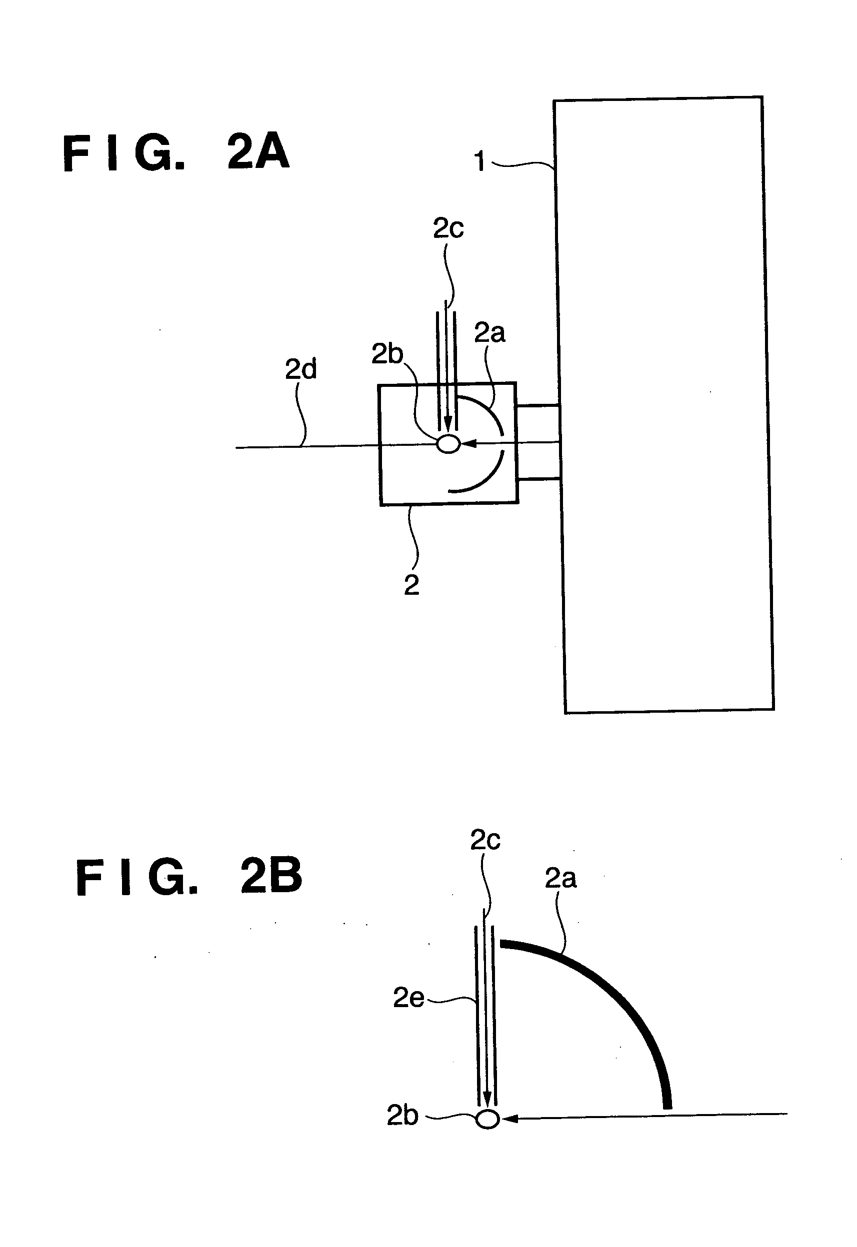
[0028] Numeral 2 denotes a light source unit having a structure in which vacuum status is maintained. FIGS. 2A and 2B show the internal structure of the light source unit 2. Numeral 2b denotes a light source indicating an actual light emission point of exposure light source. Numeral 2a denotes a light source mirror which gathers all the light from the light source 2b and reflects the light in a light emission direction, thus generates exposure light 2d. ...

fourth embodiment

[0069] Further, as the surface temperature of the radiation plate is controlled by the solid cooling element such as a Peltier element, the temperature control of the radiation plate can be efficiently realized.

[0070]

[0071] Next, an embodiment of a device fabrication method utilizing the above-described exposure apparatus will be described.

[0072]FIGS. 11A and 11B show microdevice (semiconductor chip such as an IC or LSI, a liquid crystal panel, a CCD, a thin-film magnetic head, a micromachine or the like) fabrication flows. At step 1 (circuit designing), a device pattern of a semiconductor device is designed. At step 2 (generation of exposure control data), exposure control data for the exposure apparatus is generated based on a designed circuit pattern. On the other hand, at step 3 (wafer fabrication), a wafer is fabricated by using material such as silicon. At step 4 (wafer process), called a preprocess, an actual circuit is formed on the wafer by a lithography technique using t...


PUM


Abstract

A reflection mirror apparatus, used in a reflection optical system of an exposure apparatus which performs exposure processing by guiding exposure light by reflection, has a mirror having a reflection surface to reflect the exposure light, and radiation plates for radiation-cooling provided in positions away from an outer surface of the mirror. The radiation plates are provided so as to ensure a passage area for the exposure light incident on and reflected from the reflection surface of the mirror. Further, the respective radiation plates are temperature-controlled by cooling liquid flowing through cooling pipes. Thus the temperature rise of the mirror used in the reflection optical system of the exposure apparatus can be suppressed, and the accuracy of surface form of the mirror reflection surface can be maintained.

Description

TECHNICAL FIELD [0001] The present invention relates to an exposure apparatus used in a semiconductor manufacturing proceeds, and more particularly, to an exposure apparatus with extreme ultraviolet light as an exposure light source and a reflection mirror apparatus used in a reflection optical system of the exposure apparatus. BACKGROUND ART [0002] As a projection exposure apparatus in which a reticle pattern is projected and transferred on a silicon wafer, an apparatus using extreme ultraviolet (EUV) light having a wavelength of 13 to 14 nm as an exposure light source has been proposed. As the extreme ultraviolet light is greatly attenuated when it passes through an object, an optical control system using an optical lens cannot be employed. Accordingly, in the above exposure apparatus using the extreme ultraviolet light as an exposure light source, the exposure light is controlled by plural mirrors provided in a vacuum space (reflection optical system). [0003] The reflection optic...

Claims


Application Information

Patent Timeline
IPC IPC(8): G02B5/10G02B17/00G03F7/20G21K1/06H01L21/027
CPCG02B7/1815G03F7/70175G03F7/702G21K2201/067G03F7/70891G21K1/06G21K2201/065G03F7/70233G03F7/2041
Inventor MIYAJIMA, YOSHIKAZU
Owner CANON KK
Why Eureka
Try Eureka