Information recording medium, method of manufacturing the same, and sputtering target

Inactive Publication Date: 2005-04-21
PANASONIC CORP
View PDF19 Cites 26 Cited by
  • Summary
  • Abstract
  • Description
  • Claims
  • Application Information

AI Technical Summary

Benefits of technology

[0014] Furthermore, the recording layer contains at least an oxide A-O and A (the atomic ratio of O to the material A is less than a stoichiometric composition, hereinafter referred to as having a “lower oxygen content”) and the sputtering target contains at least an oxide A-O and A, and the oxide A-O has an atomic ratio of O to A which is within the stoichiometric composition range. From the above, producing a stable thin oxide film with high reproducibility becomes possible on a mass production line.
[0015] Moreover, the information recording medium produced by the above-mentioned manufacturing method can provide media having a smaller difference of quality and having stable properties on a mass production line. Particularly, when producing an information recording medium including multiple information layers, at least one of the information layers preferably has a recording layer which is produced by the manufacturing method. In this situation, in particular, the differences due to production of the information layers need to be reduced. By applying the method of the present invention, information recording media with smaller film forming differences are obtained.
[0016] Additionally, when producing an information layer including multiple layers, it is preferable that the composition of the sputtering target used be different with regard to at least two of the processes for manufacturing the rec

Problems solved by technology

However, when performing the reactive film formation method on a mas

Method used


Image

  • Information recording medium, method of manufacturing the same, and sputtering target
  • Information recording medium, method of manufacturing the same, and sputtering target
  • Information recording medium, method of manufacturing the same, and sputtering target

Examples


example 1

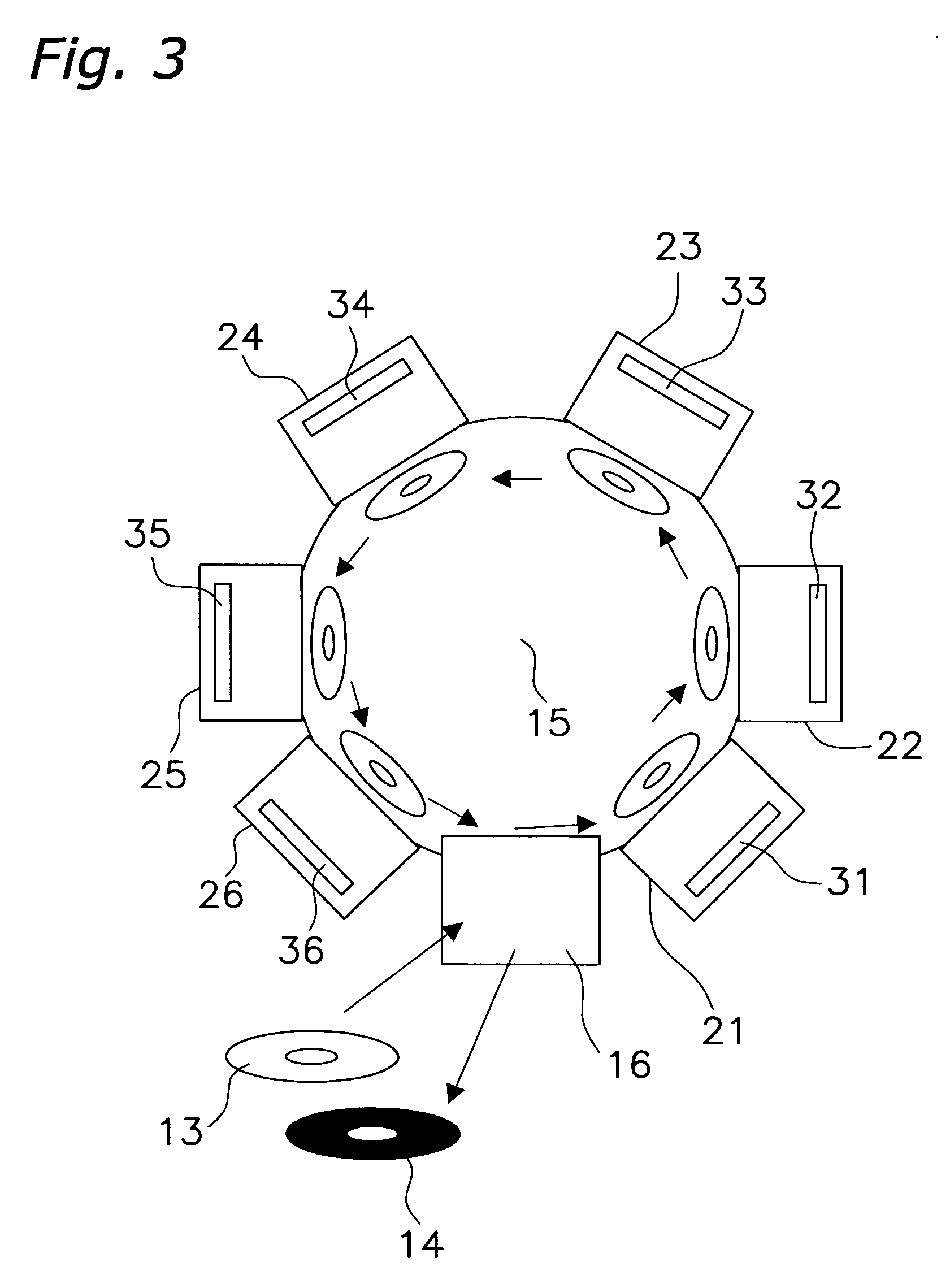
[0058] Hereafter, example 1 of the present invention will be described in detail. Here, by using the manufacturing equipment shown in FIG. 3, a thin-filmed test piece was produced to analyze the oxygen composition ratio. As the structure of the test piece, ten recording layers of Te—O—Pd having 30 nm thick were stacked on a Si substrate. The manufacturing method of the test piece is explained below. First, in the manufacturing equipment shown in FIG. 3, sputtering targets 34 and 35 that are 20 cm in diameter and composed of (TeO2)87Te5Pd8 (mol %) were placed in film formation chambers 24 and 25. The substrate used for the test piece was Si of size 12 mm×18 mm and 1 mm thick. This Si substrate was fixed to a film formation jig, and was placed in a load lock chamber 16. The film formation started at the film formation chamber 24, after passing through the film formation chambers 21, 22, 23. When forming a recording layer, Ar gas at 12 sccm and oxygen gas at 1.0 sccm was provided at a ...

example 2

[0065] (1) Example of the Present Invention

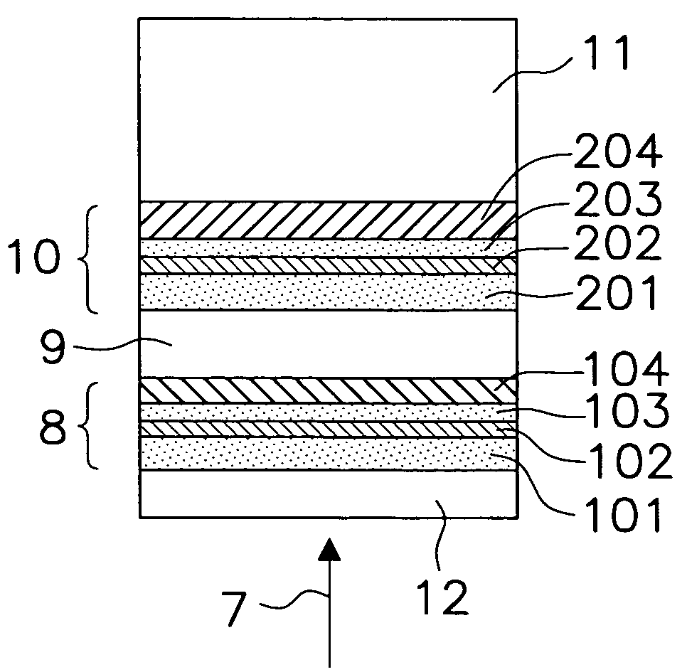
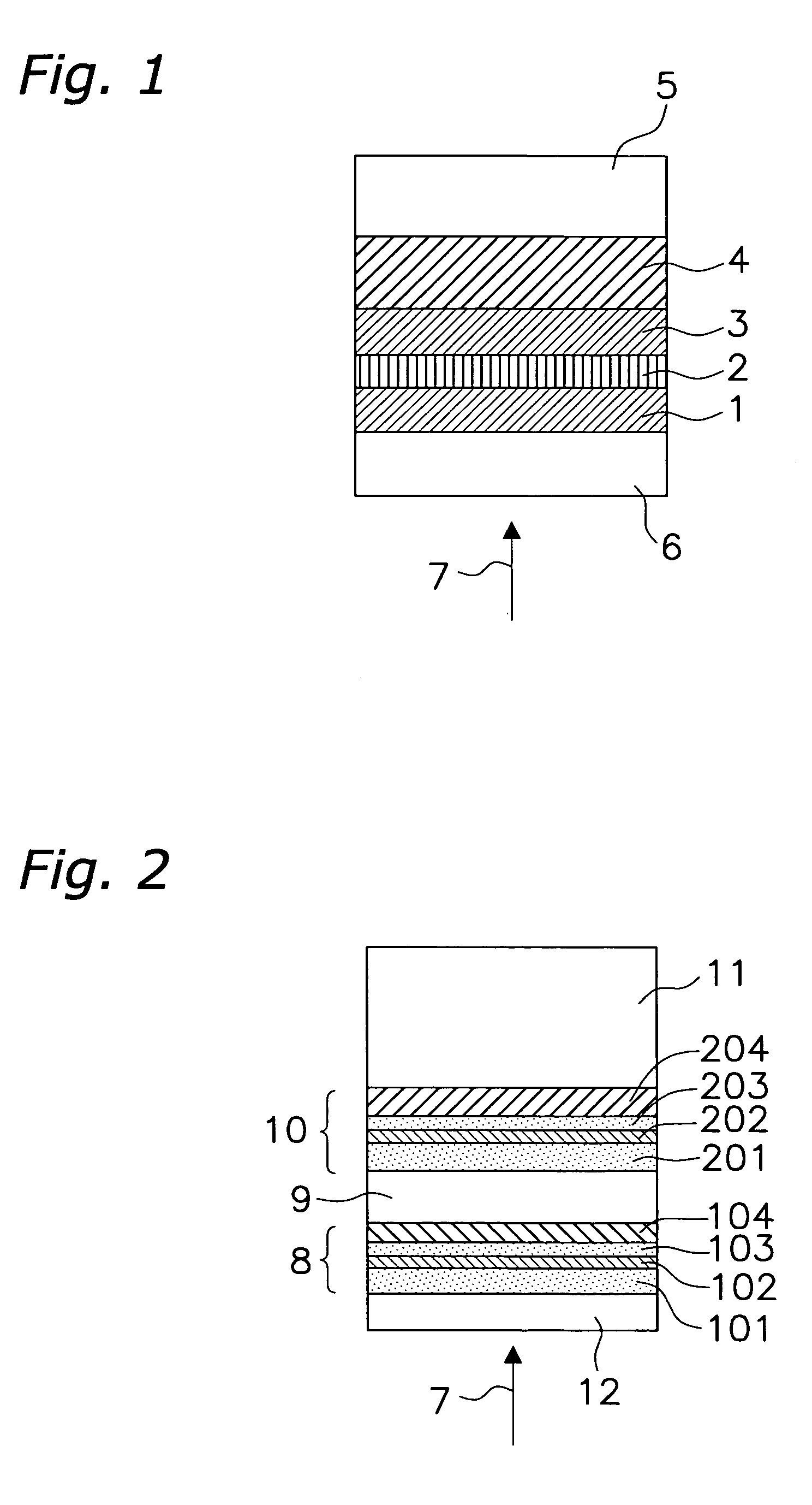
[0066] Hereinafter, example 2 of the present invention will be described in detail. Here, by using the manufacturing equipment shown in FIG. 3, an information recording medium including the layer structure shown in FIG. 1 is described. As an example, a plate of 1.1 mm thickness as the substrate 5, a disk-shaped polycarbonate resin of 120 mm diameter, a compound introducing 20 mol % SiO2 into ZnS as the protection layer 1 and 3, a material of which the main component is Te—O—Pd as the recording layer 2, and a metal compound of Al98Cr2 as the reflection layer 4 were used. As the light transparent layer 6, a disk-shaped polycarbonate resin of 0.1 mm thickness was adhered thereto with UV resin. The protection layers 1 and 3 had a film thickness of 10 nm and 17 nm respectively, the recording layer 2 was 30 nm, the reflection layer 4 was 40 nm.

[0067] In the equipment shown in FIG. 3, the reflection layer 4 is formed in the film-forming chamber ...

example 3

[0076] Hereafter, example 3 of the present invention is described in detail. In example 3, by using one of the mass-produced media in example 2, a reflectance ratio, C / N value and a jitter value were evaluated at an inner, an intermediate and an outer radial position on the disk surface, and their distribution over the entire disk was investigated.

[0077] Here, evaluation conditions for the C / N value and the jitter value are described. The same recording / reproducing equipment described in example 2 was employed. The optical systems included a laser wavelength of 405 nm, numerical aperture of the objective lens of 0.85 and a linear velocity of the medium of 9.84 m / s (a double-speed). As the modulation method of the signal, 1-7 PP modulation was used. Density corresponded to a capacity of 25 GB. To evaluate C / N, a single signal of 2 T (its mark length was 0.149 μm) was recorded on a groove using the optimum laser power for each medium. A spectrum analyzer was employed for the measurem...


PUM

PropertyMeasurementUnit
Speedaaaaaaaaaa
Compositionaaaaaaaaaa
Flow rateaaaaaaaaaa

Abstract

When manufacturing a write-once recording medium which contains an oxide having a lower oxygen content as a main component, if film formation of a recording layer is performed by introducing a large amount of oxygen into the film forming gas and the sputtering target does not contain oxygen, each medium produced has different properties, because a variation of oxygen flow in the gas easily occurs and the composition ratio of oxygen which is contained in the recording layer easily varies. To solve the problems above, an information recording medium, having at least a recording layer on a substrate and being able to record and reproduce information, contains an oxide A-O or A-O-M (A is a material which contains at least any one of Te, Sb, Ge, Sn, In, Zn, Mo and W, and M is a material which contains at least any one of a metal element, a semi-metal element, and a semiconductor-metal element), and a sputtering target used in the process of producing the layer contains at least A-O and, A and/or M. In this way, a recording layer having high reproducibility and stable properties can be produced, even in a mass production line.

Description

BACKGROUND OF THE INVENTION [0001] 1. Field of the Invention [0002] The present invention relates to an optical information recording medium able to record / reproduce information with high density and high speed, a method of manufacturing the same, and a sputtering target. [0003] 2. Description of the Prior Art [0004] As a medium which is available for recording / reproducing information with high capacity and high speed, an information recording medium such as a magnetic optical recording medium and a phase-changeable recording medium have been known. When recording information, these media take advantage of the fact that a recording material changes its optical properties with heat caused by applying a laser locally onto the material. Other than these optical information recording media, an information recording medium for recording information electrically such as a memory card has also been known. Because these information recording media have notable advantages in that random acce...

Claims


Application Information

Patent Timeline
IPC IPC(8): C23C14/00C23C14/08C23C14/34G11B7/243G11B7/26
CPCC23C14/0036C23C14/08C23C14/3414G11B2007/2432G11B7/26G11B2007/24316G11B7/243
Inventor UNO, MAYUMIKOJIMA, RIEYAMADA, NOBORU
Owner PANASONIC CORP
Why Eureka
Try Eureka