Electronic gas cooktop control with simmer system and method thereof

Inactive Publication Date: 2005-04-28
COMPUVALVE +1
View PDF12 Cites 30 Cited by
  • Summary
  • Abstract
  • Description
  • Claims
  • Application Information

AI Technical Summary

Benefits of technology

[0011] Among features provided by this invention are: a capacitive touch keyboard interface, an entirely electronic control system controlling the gas flow through modulating valves; an innovative modulating valve activated through a pulse-width-modulation (PWM) port, capable of infinitely controlling the flow of gas while also providing for an “off” position, the electrical modulating valve therefore eliminating the need for an additional in-line solenoid valve to sequence the flame “on” and “off” during simmer operation; and ceramic hot-surface igniter(s) controlled and monitored by the electronic control system, capable of constant gas re-ignition without generation of electromagnetic interference.
[

Problems solved by technology

While easily achieved in electric cooktops, simmer temperatures have until now been complicated issues for gas cooking apparatus.
With such knobs and associated infinite valves, it often becomes difficult for the user to precisely re-adjust the valve to a predetermined preferred level of BTU output and thus repeatability is rarely achieved.
Additionally, mechanical knobs are also usually susceptible to wear and tear and are often vulnerable to contaminants normally present in cooking areas, such as greases and moisture infiltration that generally find their way through open areas, necessary for the mechanical valve installation in the cooking surface.
However, very low flames have been proven hard to detect by such sensor types and are often a cause for spark igniters to unnecessarily generate discharges in response to false detection incidents.
Spark igniters are also known, by those in the industry, to emit powerful electromagnetic interferenc

Method used


Image

  • Electronic gas cooktop control with simmer system and method thereof
  • Electronic gas cooktop control with simmer system and method thereof
  • Electronic gas cooktop control with simmer system and method thereof

Examples


Example

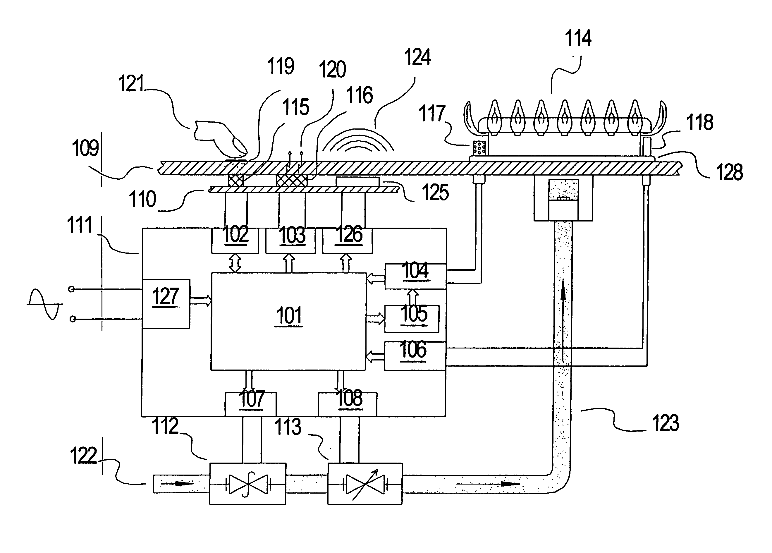
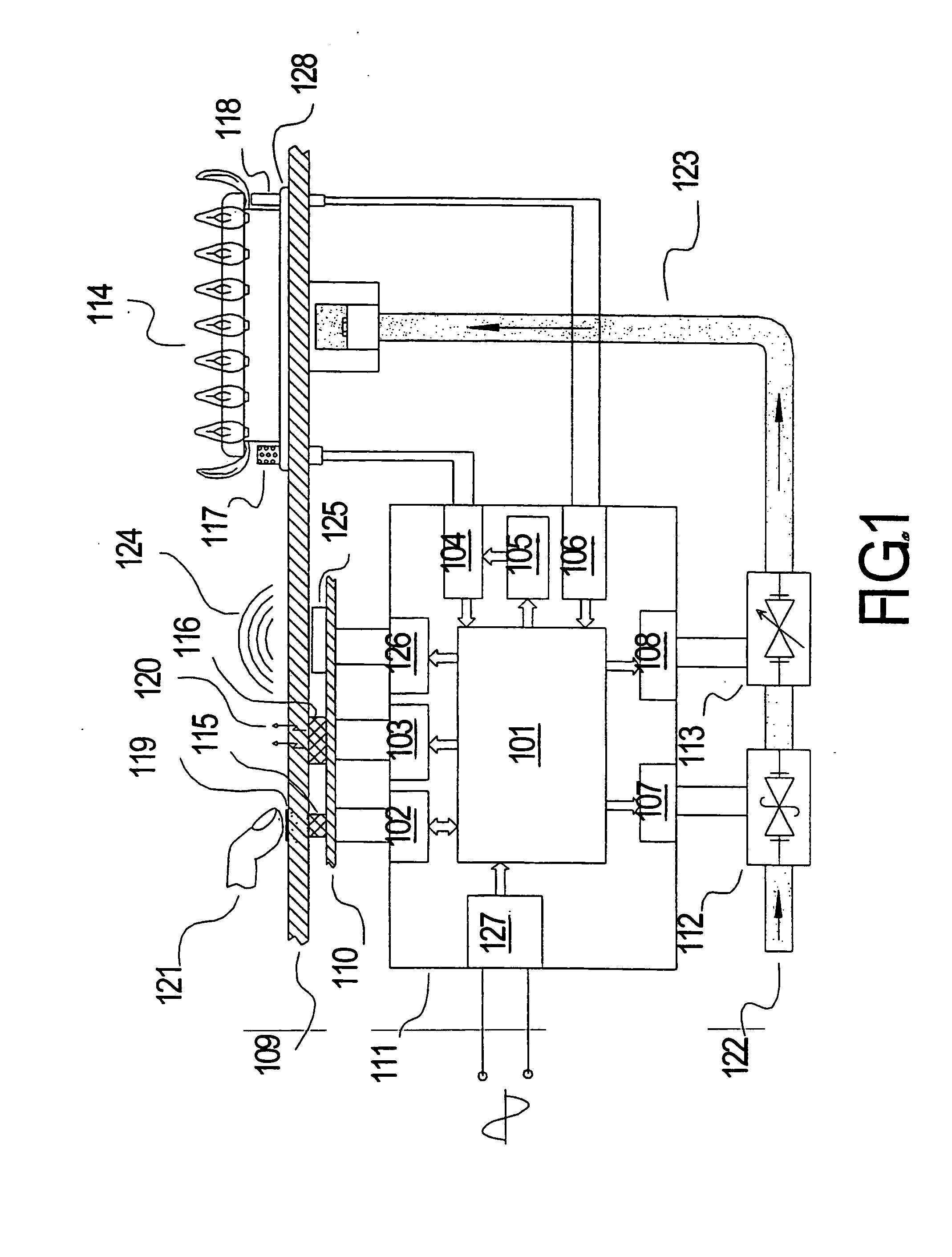
[0015]FIG. 1 is a basic block diagram of a cooktop system made in accordance with this invention. The cooktop shown in FIG. 1 has one or more gas burner(s) 114 placed on a ceramic glass panel 109; one electronically controlled in-line safety gas valve 112; one or more electronically controlled in-line modulating valve(s) 113; a gas line conduit 123 to conduct gas from the main gas supply to the burner(s) under control through the in-line valves; a user interface panel 110 preferably placed in registry with a silk-screened portion of a ceramic glass panel 109; one or more temperature sensor(s) 118; one or more hot-surface igniter(s) 117; and a controller 111 operative to control each of the gas valves in accordance with the user's selection entered at the user interface, the apparatus being controlled by a suitably programmed microcontroller 101.

[0016] The user interface panel 110, placed in registry with a silk-screened portion of a ceramic glass panel 109, preferably firther inclu...


PUM


Abstract

An electronically activated gas cooktop control system, responsive to a touch-sensitive user interface, and capable of providing a predetermined range of cooking and simmer levels of BTU output, has two complementary heating modes of operation A first heating mode of operation is provided to produce a wide selection of simmer levels of BTU output, by electronically sequencing a solenoid-operated modulating gas valve “on” and “off”, at a predetermined level of flame. A second cooking mode of operation is provided by electronically modulating the level of flame, through use of a pulse-width-modulation (PWM) output signal to produce a wide selection of cooking levels of BTU output. An igniter system capable of insuring proper ignition of gas without generating harmful electromagnetic interference is also provided.

Description

TECHNICAL FIELD OF INVENTION [0001] This invention relates to control of gas appliances in general and more specifically to an electronically actuated gas cooktop flame proportioning control with flame sequencing simmer system. BACKGROUND ART [0002] While easily achieved in electric cooktops, simmer temperatures have until now been complicated issues for gas cooking apparatus. Conventional gas cooktops are generally operated by using manually activated mechanical actuator knobs, with infinitely varying settings of the flow of gas by rotating associated gas proportional valves. Most often, adjustment of cooking level is achieved by comparing level indicators printed on the knob, to a fixed pointer printed on the cooktop surface, immediately surrounding the knob. With such knobs and associated infinite valves, it often becomes difficult for the user to precisely re-adjust the valve to a predetermined preferred level of BTU output and thus repeatability is rarely achieved. This effect ...

Claims


Application Information

Patent Timeline
IPC IPC(8): F23N1/00F23N5/10F23N5/20F24C3/12
CPCF23N1/005F23N5/10F23N5/203F23N2027/10F23N2027/36F23N2027/42F24C3/126F23N2031/22F23N2035/16F23N2037/02F23N2037/10F23N2041/08F23N2031/20F23N2227/10F23N2227/36F23N2227/42F23N2231/20F23N2231/22F23N2235/16F23N2237/02F23N2237/10F23N2241/08H03K17/9622H03K2217/96066H03K2217/960785
Inventor REPPER, PIERRE P.SHUTE, ALAN B.SHUTE, CHRISTA B.SHUTE, SUZANNE J.OLSON, ALLEN L.ZHOU, FENG
Owner COMPUVALVE
Why Eureka
Try Eureka