

Waveplate and optical devices formed using mesogen-containing polymer
a technology of mesogen-containing polymer and wave plate, which is applied in the direction of optical elements, polarising elements, instruments, etc., can solve the problems of birefringence in stressed polyimide films, disrupting the degree of organization that the material can achieve, and the presence of these moieties is ordinarily deleterious to the degree of birefringence that can be developed
- Summary
- Abstract
- Description
- Claims
- Application Information
AI Technical Summary
Benefits of technology
Problems solved by technology
Method used
Image

Examples
example 1
[0181] A first waveplate polymer is formulated using 4 parts PFMB, 1 part C6BP, and 5 parts bis-ADA in m-cresol to yield a random polymer having the general formula shown in FIG. 6. The copolymer is formed using the following formulation.
[0182] PFMB (15.18 g, 47.41 mmol), C6BP (9.21 g, 11.86 mmol) and m-cresol (345 g) were added to a 500 ml three-necked round bottom flask equipped with a mechanical stirrer, a nitrogen inlet, and a distillation head. After the diamine monomers dissolved in m-cresol, 4,4′-(4,4′-isopropylidenediphenoxy)bis(phthalic anhydride) (bis-ADA) (30.24 g, 58.10 mmol) was added and the mixture was stirred at room temperature for one day. Isoquinoline (0.5 ml) was added and the reaction temperature was raised to 202° C. for 15 hours. After the solution was allowed to cool to room temperature, it was slowly added to methanol to precipitate the polymer. The polymer was dissolved in chloroform and re-precipitated in methanol and dried in vacuum oven.
[0183] This wav...
example 2
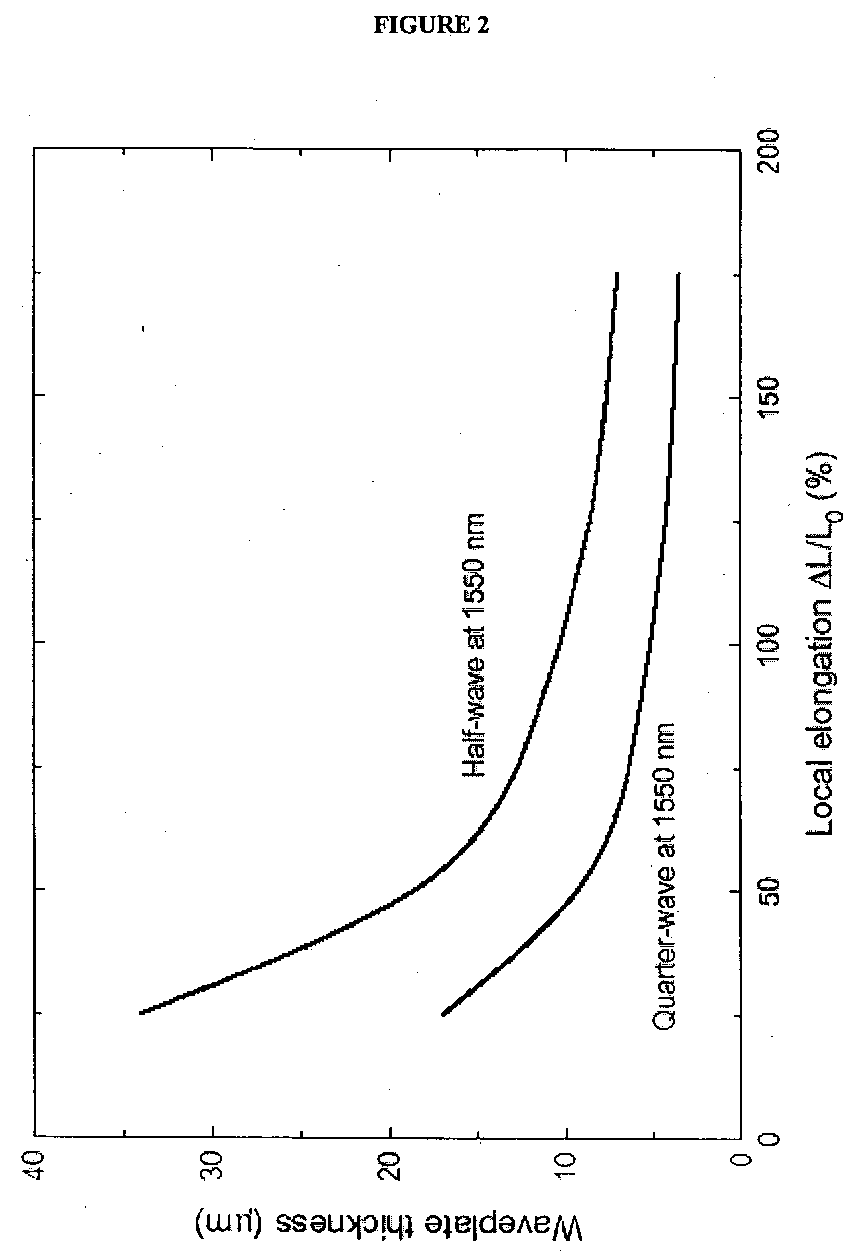
[0185] A polymer film is formed, and heated and stretched according to Example 1. After the film is stretched it is annealed in an oven at 145° C. for two hours. The thickness of the pre-stretched film and the degree of elongation during the stretch are chosen such that after the film is stretched and annealed, the thickness of the film is approximately 15.6 μm, and the retardance is one half wave at a wavelength of about 1550 nm. A waveplate is cut from the film at a 45 degree angle to the stretch direction. The waveplate is tested by illuminating it with polarized light at approximately 1550 nm wavelength polarized along the direction of the cut of the waveplate (and thus at about a 45 degree angle to the stretch axis of the waveplate). The light that is transmitted through the waveplate is passed through a polarizer used as an analyzer. The optical power transmitted through the analyzer is measured with the analyzer perpendicular to the polarization of the input laser light, and ...
example 3
[0186] Two waveplates according to Example 2 are formed, one with retardance 0.47 waves and one with retardance 0.67 waves at about 1550 nm wavelength. The waveplates are tested for birefringence and then baked on a hotplate at 125° C. for 2 hours, retested, and then baked several more times, being retested after 8, 24, 48, 96, 192, and 288 hours on the hotplate at 125° C. During this test, no measurable changes are detected in waveplate retardance, demonstrating that the waveplates are thermally stable up to 125° C.
PUM
| Property | Measurement | Unit |
|---|---|---|
| heat resistance | aaaaa | aaaaa |
| thick | aaaaa | aaaaa |
| thick | aaaaa | aaaaa |
Abstract
Description
Claims
Application Information