Semiconductor chip package having decoupling capacitor and manufacturing method thereof
a semiconductor and capacitor technology, applied in the field of semiconductor chip packaging having an improved deco, can solve the problems of noise and signal propagation delay, performance degradation, diminishing the beneficial effect of decoupling capacitors, etc., to improve the decoupling capacitor, reduce parasitic resistance and inductance, and shorten the path to a semiconductor device
- Summary
- Abstract
- Description
- Claims
- Application Information
AI Technical Summary
Benefits of technology
Problems solved by technology
Method used
Image
Examples
first exemplary embodiment
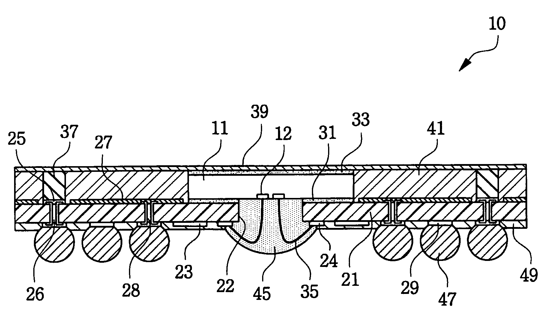
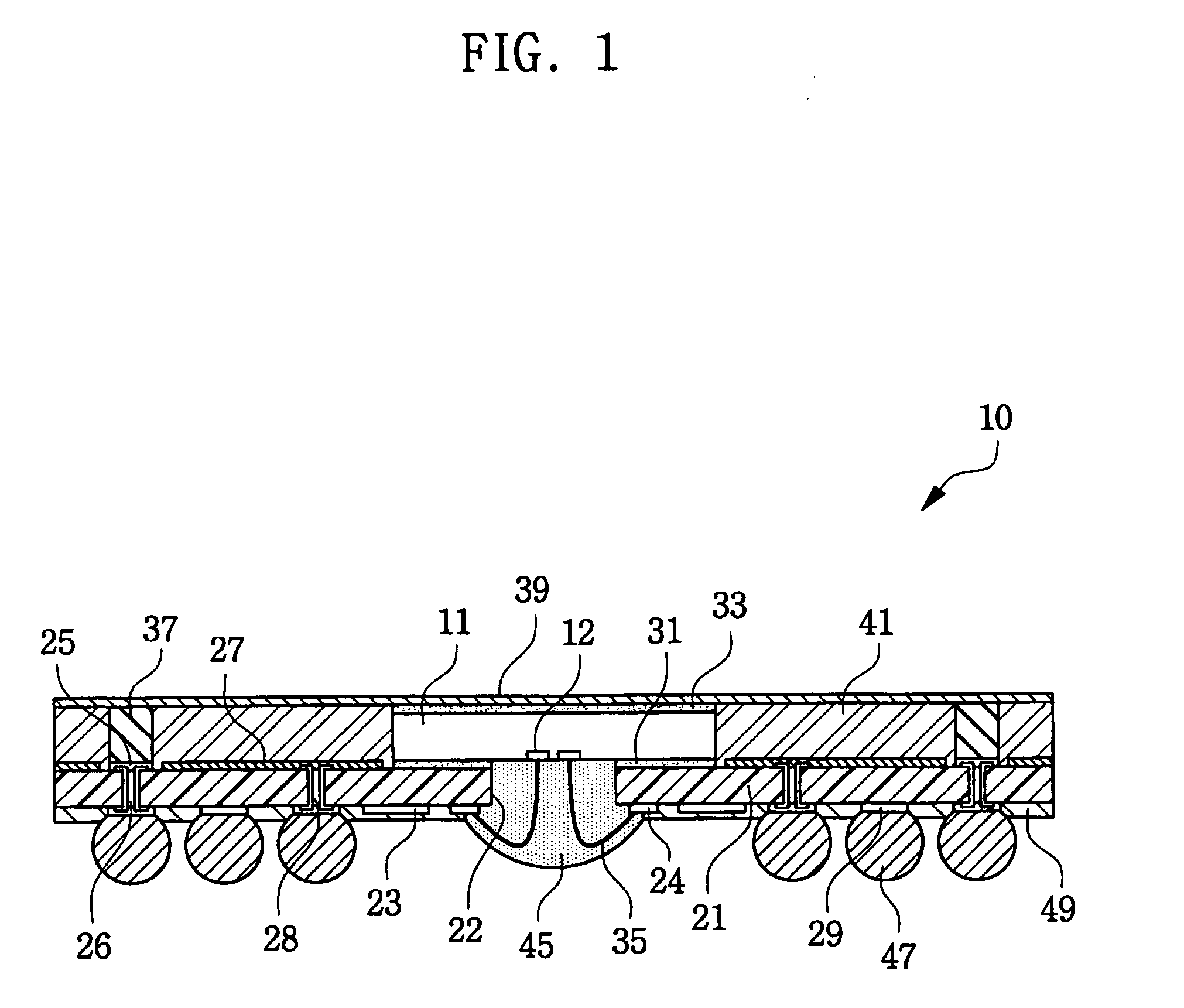
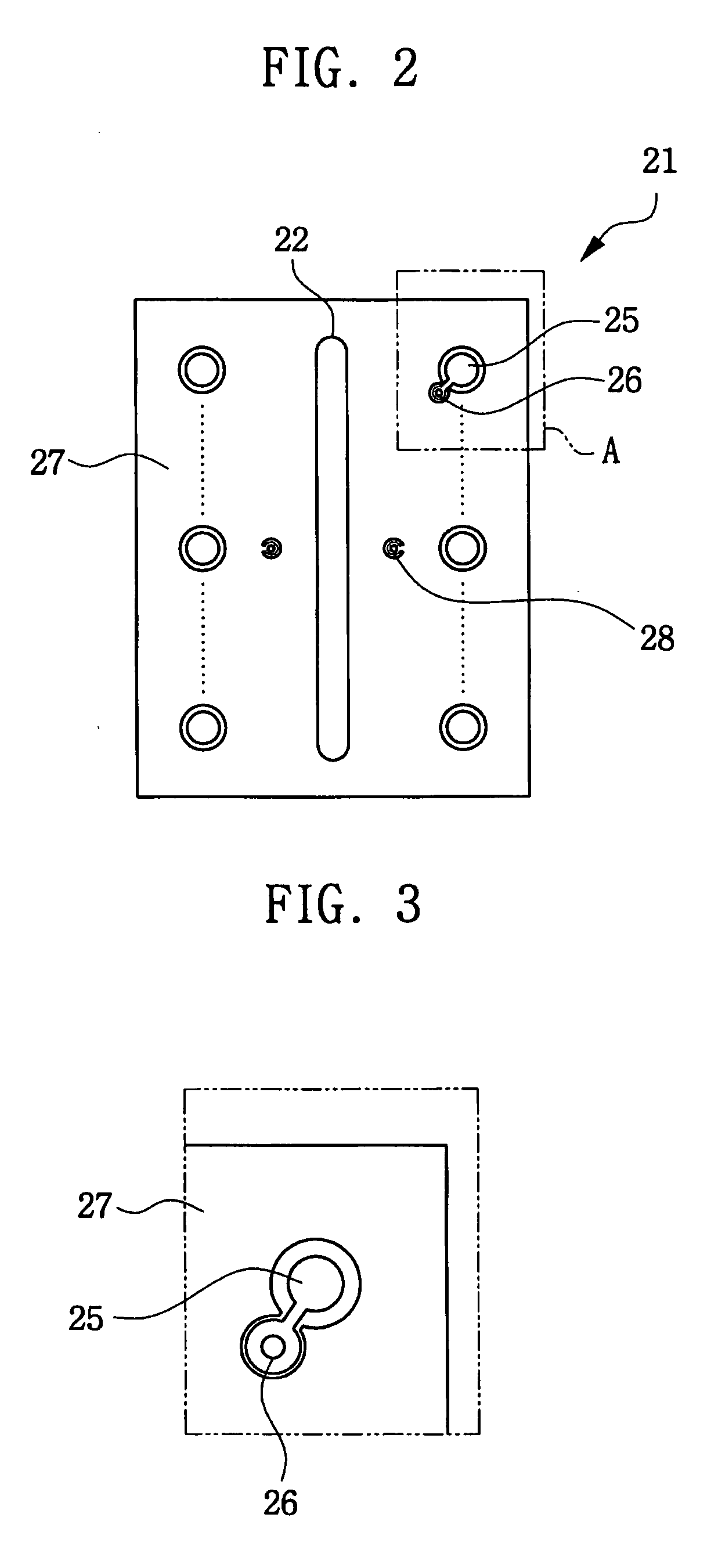
[0022]FIG. 1 illustrates, in a cross-sectional view, a semiconductor chip package 10 in accordance with a first exemplary embodiment of the present invention. Further, FIG. 2 illustrates a plan view of a substrate 21 as used in the semiconductor chip package 10 shown in FIG. 1; and FIG. 3 shows an enlarged view of section “A” in FIG. 2.
[0023] Package 10 includes a semiconductor chip 11 of a center pad type. That is, chip pads 12 are formed along a central line on an active surface of chip 11. The active surface of the chip 11 faces a substrate 21 and is attached thereto. The chip pads 12 of chip 11 are electrically coupled to the substrate 21 through bonding wires 35. Solder balls 47 are formed on the substrate 21 and are used as external connection terminals of the package 10. In particular, the package 10 has a decoupling capacitor composed of a power plane 27, a ground plane 39, and a dielectric layer 41.
[0024] The substrate 21 in this embodiment has an opening 22 formed in a c...
second exemplary embodiment
[0040]FIG. 5 shows, in a cross-sectional view, a semiconductor chip package 110 in accordance with a second exemplary embodiment of the present invention.
[0041] Referring to FIG. 5, a package 110 of this embodiment includes a semiconductor chip 111, which is attached to a substrate 121 in a flip-chip fashion through chip bumps 113. Solder balls 147 are formed under the substrate 121 and are used as external connection terminals of the package 110. The package 110 has a decoupling capacitor composed of a power plane 127, a ground plane 139, and a dielectric layer 141.
[0042] Instead of wire-bonding technique in the aforementioned embodiment, a flip-chip technique may be used to electrically connect the chip 11 and the substrate 121. Namely, the chip 111 and the substrate 121 are electrically connected through chip bumps 113 provided on chip pads (not shown). Chip bumps 113 are directly joined to substrate pads 124 disposed on the top surface of the substrate 121. Unlike the previous...
third exemplary embodiment
[0049]FIG. 7 shows, in a cross-sectional view, a semiconductor chip package 311 in accordance with a third exemplary embodiment of the present invention. Further, FIG. 8 shows, in a cross-sectional view, a substrate 421 exemplarily used in the package of this embodiment of the present invention, and FIGS. 9A and 9B show respectively, in plan views, top and bottom surfaces of the substrate 421 shown in FIG. 8.
[0050] Referring to FIG. 7, the package 311 of this embodiment includes two stacked semiconductor chips 311 and 411, which have chip bumps 312 and 412 and are attached to first and second substrates 321 and 421, respectively, in a flip-chip fashion through the chip bumps 312 and 412. Solder balls 347 are formed under the first substrate 321 and are used as external connection terminals of the package 310. The package 310 has two decoupling capacitors each composed of a power plane 327 and 427, a ground plane 339 and 439, and a dielectric layer 341 and 441.
[0051] The first chip...
PUM
 Abstract
Description
Claims
Application Information
 - R&D
- Intellectual Property
- Life Sciences
- Materials
- Tech Scout
- Unparalleled Data Quality
- Higher Quality Content
- 60% Fewer Hallucinations
Browse by: Latest US Patents, China's latest patents, Technical Efficacy Thesaurus, Application Domain, Technology Topic, Popular Technical Reports.
© 2025 PatSnap. All rights reserved.Legal|Privacy policy|Modern Slavery Act Transparency Statement|Sitemap|About US| Contact US: help@patsnap.com


