System and method for detecting bioanalytes and method for producing a bioanalyte sensor

a bioanalyte and sensor technology, applied in the field of bioanalyte detection systems and bioanalyte sensors, can solve the problems of minimal invasiveness and no non-invasive method for blood glucose sensing presently available, and achieve the effect of preventing leaching

Inactive Publication Date: 2005-06-02
SCHULTZ JEROME +1
View PDF2 Cites 201 Cited by
  • Summary
  • Abstract
  • Description
  • Claims
  • Application Information

AI Technical Summary

Benefits of technology

[0007] This invention makes such a protein by incorporating optical reporter groups into a fusion protein that contains a specific and reversible binding site (B) for an analyte of interest, such as glucose, in such a manner that the spatial separation between the optical reporter moieties in the protein changes when the ligand binds to section B of the fusion protein. At least one of the optical reporter moieties (A) is a fluorescent protein (such as a green fluorescent protein). The other moiety (C) is a protein that has an absorption spectrum that overlaps the emission of A. The fusion molecule is designed such that the distance between A and C is less than 100 Angstroms so that the hybrid protein exhibits a change in fluorescence energy transfer (FRET) when the analyte binds to B. Moiety C can be a colored protein (such as hemoglobin or chlorophyll), in which case one can monitor the change in emitted fluorescence intensity or fluorescence lifetime of moiety A to monitor the extent of analyte binding to B that is related to the free concentration of analyte in the surrounding fluid. See FIG. 1. Alternatively, moiety C can be another fluorescent protein, selected such that the adsorption s

Problems solved by technology

Developing a minimally invasive glucose monitor biosensor to assist in the treatment of diabetes has been a challenge to the analytical community.
1994), no method is presently available for non-invasively sensing of blood glucose (Tolosa, et al.
Furth

Method used


Image

  • System and method for detecting bioanalytes and method for producing a bioanalyte sensor
  • System and method for detecting bioanalytes and method for producing a bioanalyte sensor
  • System and method for detecting bioanalytes and method for producing a bioanalyte sensor

Examples


Embodiment Construction

Method of Creating Indicator Fusion Protein

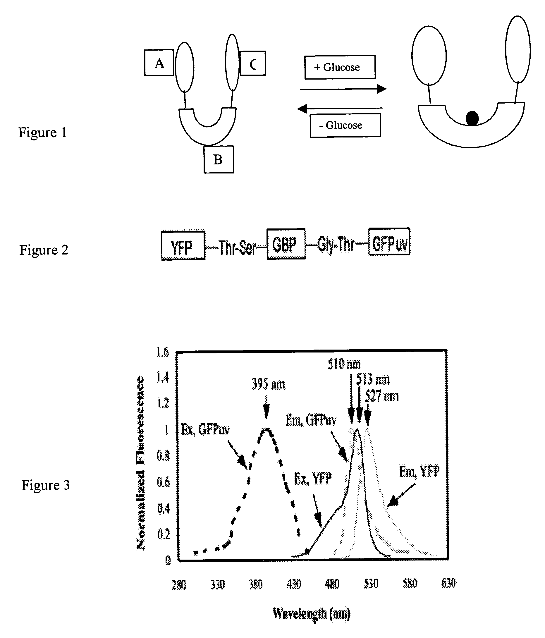
[0017] In one preferred embodiment of the present invention, to combine the brightness of fluorescent protein with the targeted molecular indicator, we use a green fluorescent protein isolated from the bioluminescent jelly Aeqorea Victoria (Shimomura, et al., 1962). The cloning of the wild type GFP gene and its subsequent expression in heterologous systems established GFP as a novel genetic reporter system (Prasher, et al. 1992; Chalfire, et al., 1994). Several GFP chromophore variants with shifted excitation and emission wavelengths have been developed by mutagenesis (Heim, et al., 1994; Cormack, et al., 1996), which can serve as donors and acceptors for fluorescence resonance energy transfer (FRET).

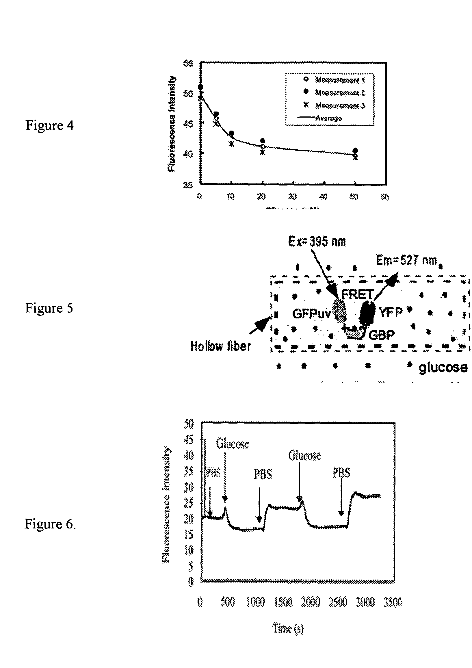
[0018] As an example of the general class of bioanalyte reporter proteins the present invention presents a new hybrid glucose binding protein that provides changes in fluorescence when glucose binds. This construct utilizes the conformationa...


PUM


Abstract

The present invention discloses an indicator protein, and a method for making such a fusion protien, having a first binding moiety having a binding domain specific for a class of analytes that undergoes a reproducible allosteric change in conformation when said analytes are reversibly bound; a second moiety and third moiety that are covalently linked to either side of the first binding moiety such that the second and third moieties undergo a change in relative position when an analyte of interest molecule binds to the binding moiety; and the second and third moieties undergo a change in optical properties when their relative positions change and that change can be monitored remotely by optical means. The present invention also discloses a system and method for detecting glucose that uses such a fusion protein in a variety of formats including a subcutaneously and in a bioreactor.

Description

RELATED APPLICATION [0001] This patent claims priority from provisional application 60 / 405,920 entitled, “System and Method for Detecting Bioanalytes and Method for Producing a Bioanalyte Sensor,” filed Aug. 26, 2002.SEQUENCE LISTING [0002] Applicants submit herewith a Sequence Listing in computer and paper form, in accordance with 37 C.F.R. §1.821-1.825. The content of the paper and computer readable copies of the Sequence Listing submitted in accordance with 37 C.F.R. §1.821(c) and (e) are the same. BACKGROUND OF THEE INVENTION [0003] Developing a minimally invasive glucose monitor biosensor to assist in the treatment of diabetes has been a challenge to the analytical community. Despite intensive efforts, mostly based on near infrared spectroscopy (Heise, et. al. 1994), no method is presently available for non-invasively sensing of blood glucose (Tolosa, et al. 1999). Most approaches to this problem have explored minimally invasive techniques. A wide variety of approaches have bee...

Claims


Application Information

Patent Timeline
IPC IPC(8): G01N33/543G01N33/58G01N33/66
CPCG01N33/66G01N33/582
Inventor SCHULTZ, JEROMEYI, KAIMING
Owner SCHULTZ JEROME
Why Eureka
Try Eureka