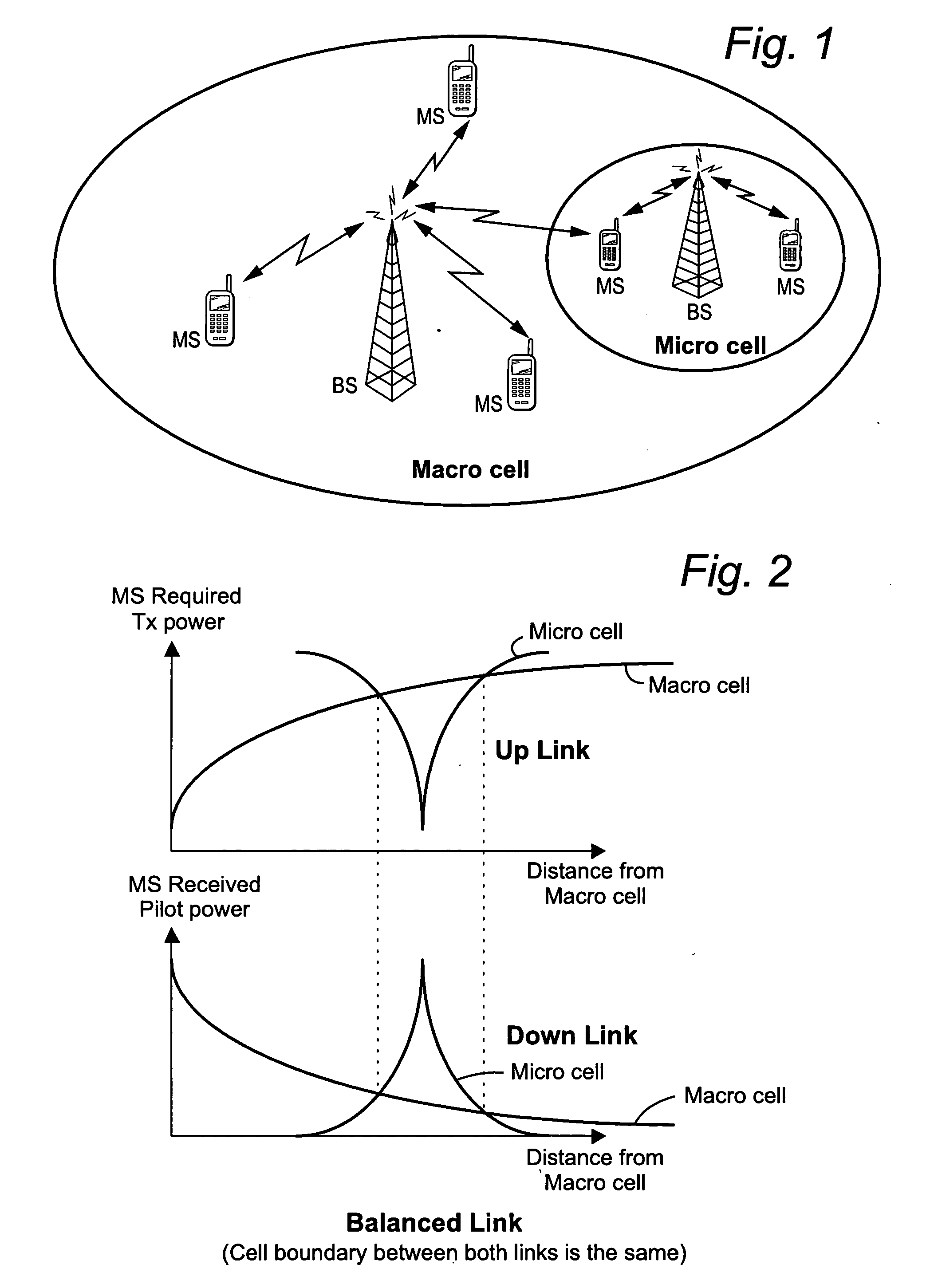
[0001] Hierarchical cellular communications systems employ different size cells to provide both wide-coverage, basic-service (macro cell) and high-quality, high-capacity
radio coverage in smaller areas (micro cell). Micro cells are useful in specific areas where increased capacity is needed. For example, micro cells may be located to serve areas of concentrated traffic within the macro cell or to provide a
high data rate service. A micro cell uses a low-height antenna and a low base station transmit power which result in a
small cell and a short
frequency reuse distance, thereby increasing capacity. Additional benefits of a smaller cell include a longer talk-time (battery
life time) for the user since mobile stations will likely use a substantially lower uplink transmit power to communicate with a micro cell base station than with a base station in a larger macro cell which is likely farther away.
[0004] Alternatively, the macro and micro cells may employ the same frequency which allows
soft handover and macro diversity to be used and provides more capacity. There are several well known advantages to
soft handover in mobile communications including make-before-break handover to sustain continuous service at cell boundaries and compensation for
fading and other disturbances to the received
signal. And all systems hope to increase capacity.
[0009] The present invention solves these and other problems in the context of a HCS by using an unbalanced link.
Macro and micro cells in the HCS use the same frequency /
frequency band to increase capacity and attain diversity benefits as compared to using different frequencies / frequency bands. Complicated and time-consuming inter-frequency handover, which may sometimes be unstable, is also avoided. The micro cell downlink coverage is reduced so that the radio uplink and downlink for the HCS are purposefully unbalanced. A smaller micro cell in the downlink may be beneficial in terms of providing stable service to a highly-loaded but relatively-small service area.
[0011] Handovers to the micro cell in an unbalanced link, being based on detected or otherwise determined micro cell pilot powers, occur less / later than if a balanced link was used. Indeed, some potential handovers will not even occur. Although the micro cell downlink coverage is reduced with an unbalanced link, mobiles that would be served by the micro cell with a balanced link are adequately served by the macro cell. And an unbalanced link offers more stable HCS service in the micro cell and provides greater overall capacity
gain for the HCS
system. Moreover, the unbalanced link offers the micro cell base station a
downlink transmission power “margin.” Reduced coverage of the micro cell base station means that the
total transmission power from the micro cell base station is reduced. The base station transmission power to a relatively close
mobile station is relatively small compared with that to a mobile station relatively far from the base station. As a result, the micro cell base station has some additional margin / flexibility to increase its maximum transmit power if needed to reach a mobile station suffering excessive interference with acceptable
signal power and quality.
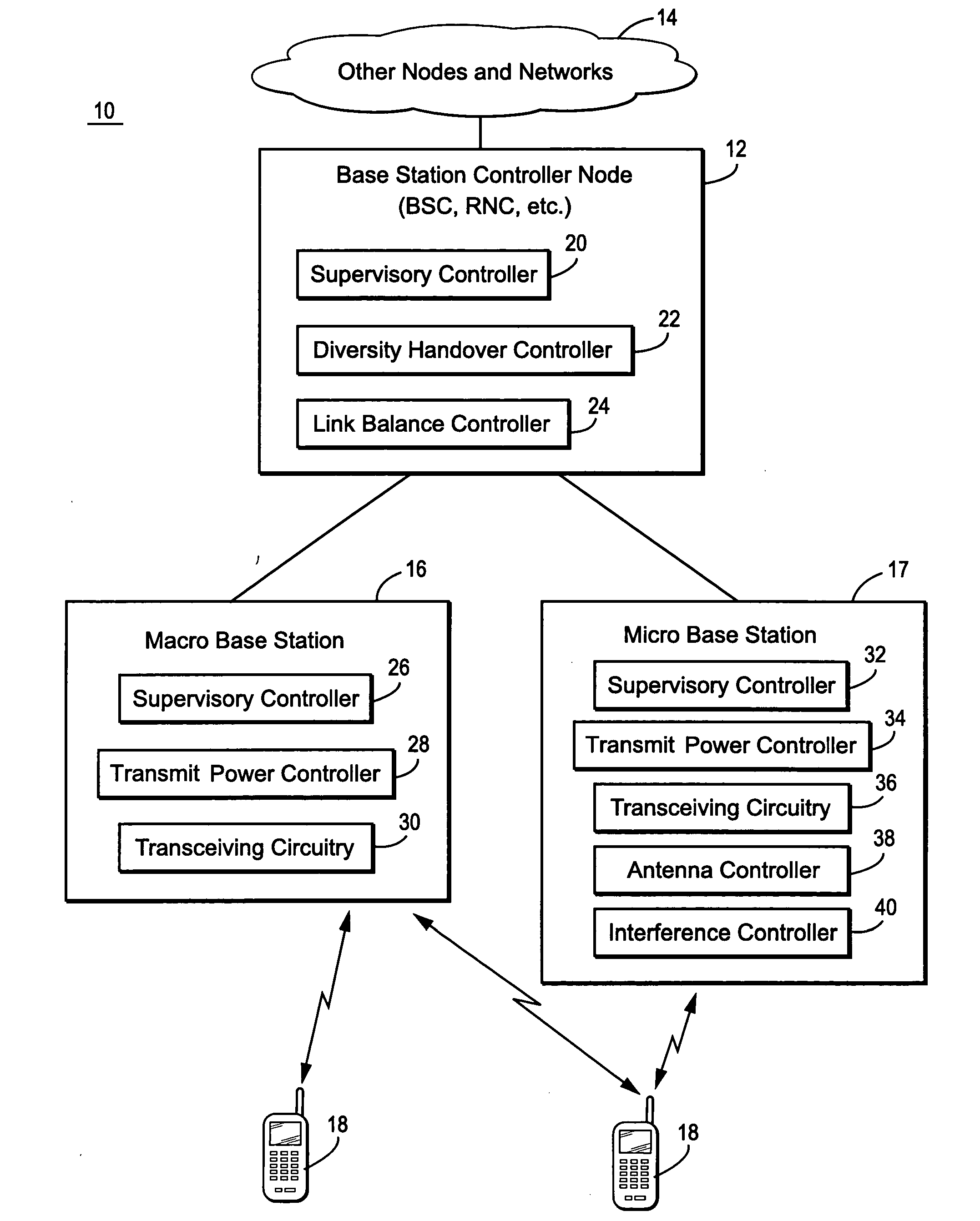
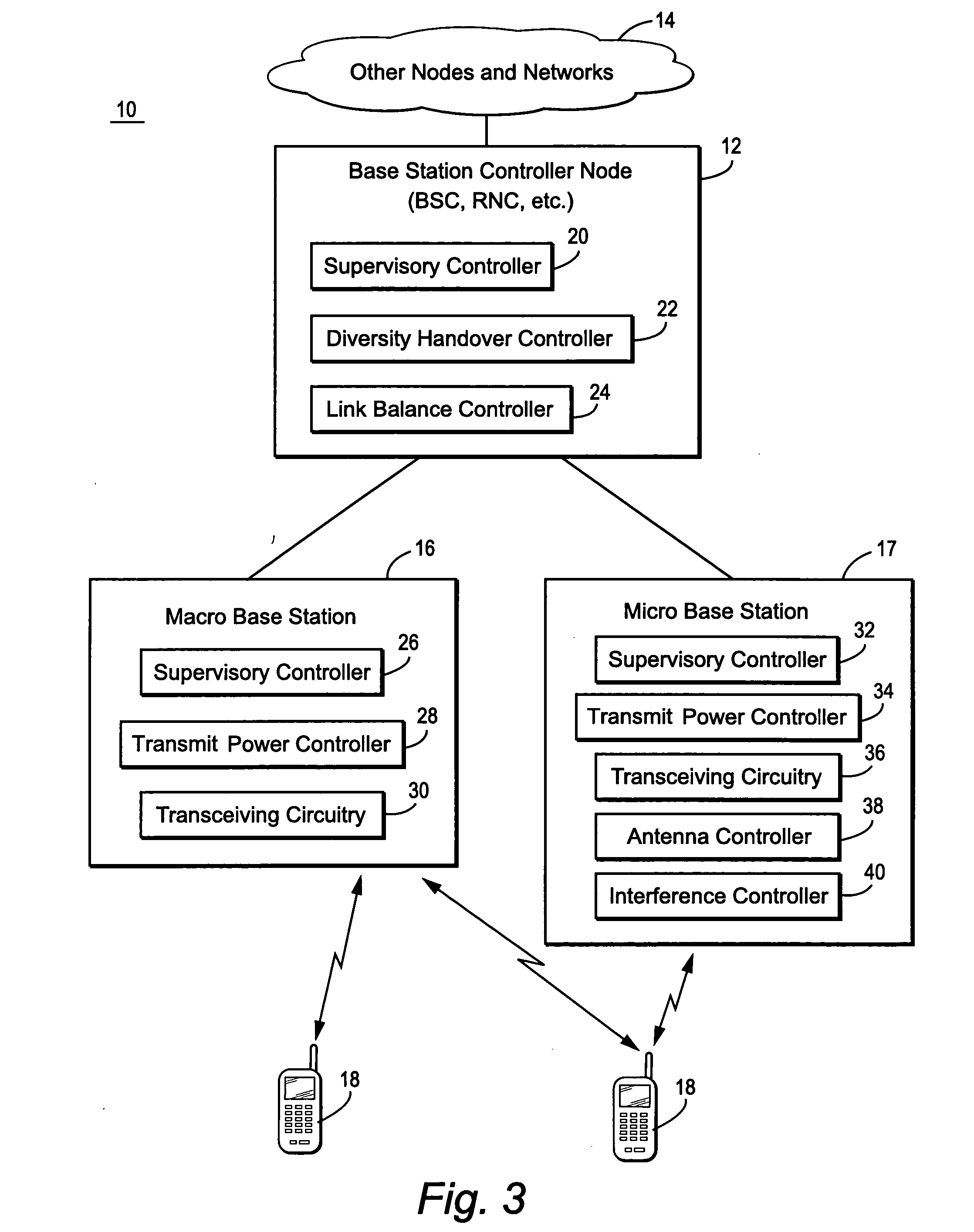
[0013] Three, non-limiting, example techniques for implementing an unbalanced link are described. First, the radio network may directly instruct the micro cell base station to reduce the
power level of its
pilot signal. Second, the radio network may instruct the micro cell base station to “tilt” the antenna corresponding to the micro cell pilot to decrease its
azimuth angle thereby effectively decreasing the range of the
pilot signal. Third, the
radio network controller may send an offset value to one or more mobile stations near the micro cell. Those mobiles use that offset to mathematically reduce the detected
pilot power from the micro base station. Because the received micro cell
pilot power is decreased by that offset, the mobile perceives the micro cell base station as farther away, and is thus more likely to be serviced by the macro base station. Alternatively, the radio network may selectively apply the offset to mobile reported pilot powers to achieve a similar effect. These latter two “indirect” approaches may be desirable because they do not actually reduce the
pilot power level. A strong pilot signal is necessary for accurate channel
estimation and signal
demodulation. But these two approaches still effect a reduced downlink micro
cell size.
[0015] Yet another inventive feature relates to
high velocity mobile stations. If the speed of the mobile station exceeds a threshold, the radio network controller may prevent handover of the mobile connection to the micro cell by reducing (or reducing by a larger amount) the downlink range of the micro cell. A smaller micro cell downlink reduces the chance that a fast moving mobile will be handed over to the micro cell and then quickly handed right back to the macro cell. Overhead, signaling, and associated bandwidth reduction for the macro-to-micro-to-macro cell handovers are avoided.

