Method for joining at least a first member and a second member, lithographic apparatus and device manufacturing method, as well as a device manufactured thereby
a technology of lithographic apparatus and manufacturing method, which is applied in the direction of glass shaping apparatus, duplicating/marking methods, lamination, etc., can solve the problems of second member, fair failure chance, and unsatisfactory degradation of the bonding surface of the joined member
- Summary
- Abstract
- Description
- Claims
- Application Information
AI Technical Summary
Benefits of technology
Problems solved by technology
Method used
Image
Examples
first embodiment
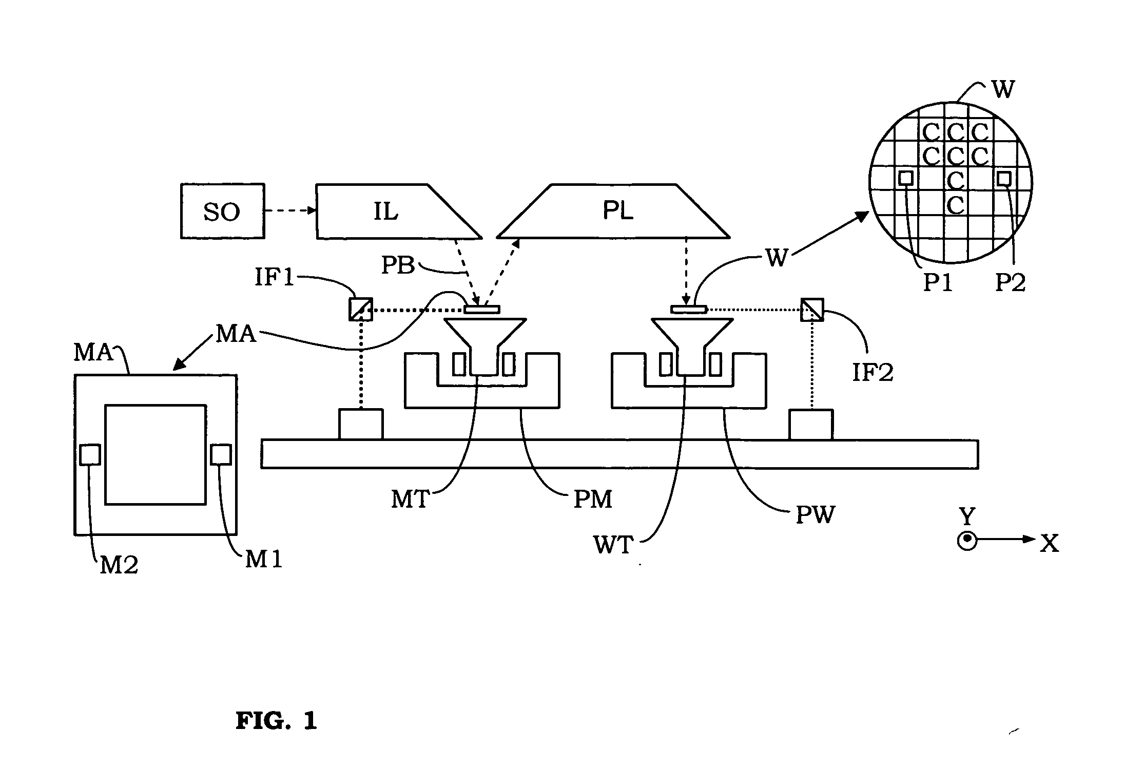
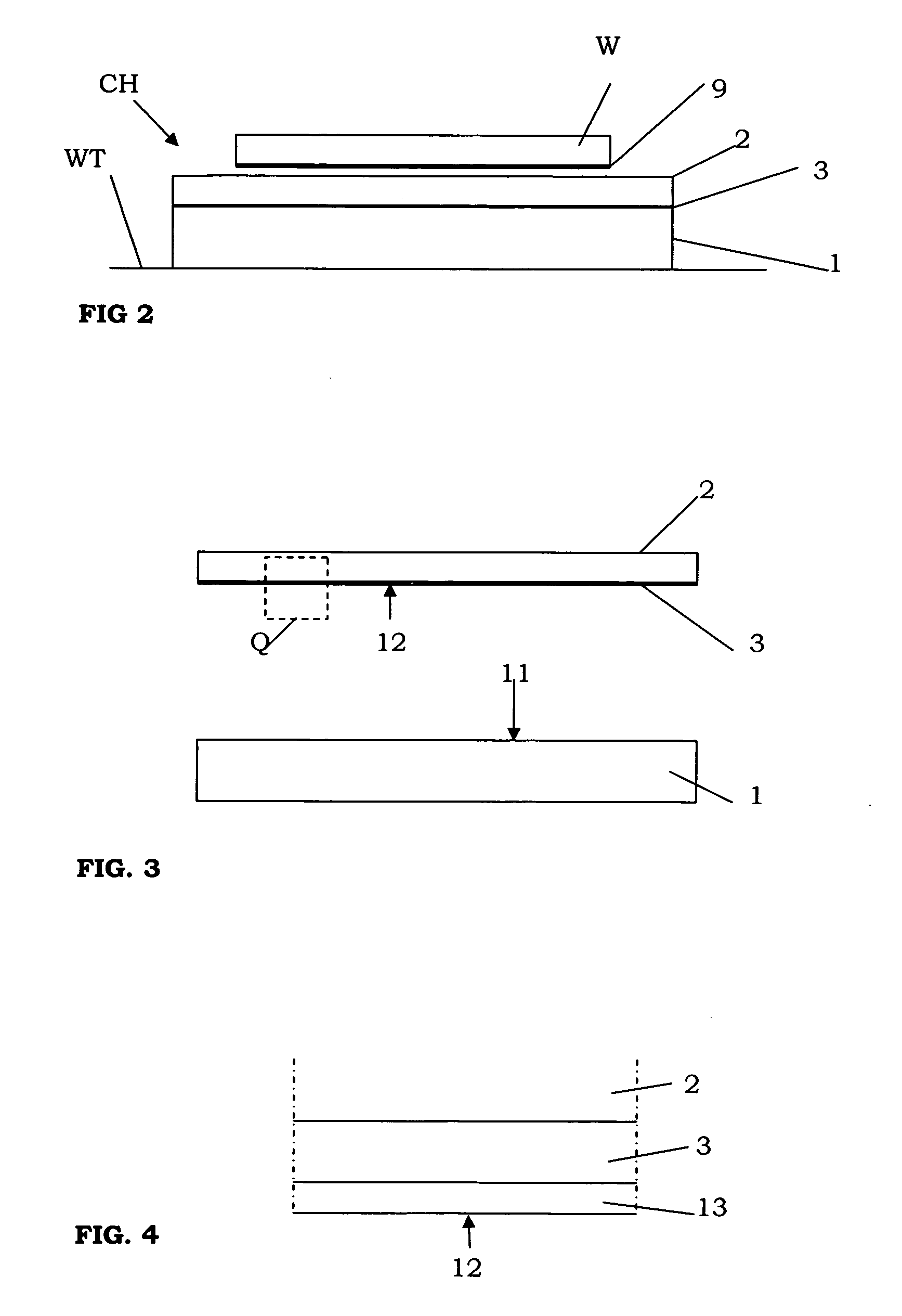
[0064]FIG. 2 shows the invention, comprising a chuck CH which may be used in the apparatus of FIG. 1. The chuck CH is not shown in FIG. 1. In the present embodiment, the chuck CH is used to hold substrates W onto the substrate table WT by electrostatic force. The chuck may also be used, for example, to hold the reticle onto the reticle table.
[0065] The chuck CH of the first embodiment comprises a first member 1 and a second member 2. A first electrode 3 extends between the first and second member 1, 2. The first electrode is an electrically conductive layer 3. The electrically conductive layer 3 preferably comprises one or more suitable conducting substances, for example, copper, aluminium, titanium, silver, gold, chrome, alloys thereof, other metals, and / or other alloys.
[0066] Each of the members 1, 2 comprises a material which is selected from the group consisting of: ultra low expansion glass, and ultra low expansion glass ceramics. In the present embodiment, the first member 1 ...
third embodiment
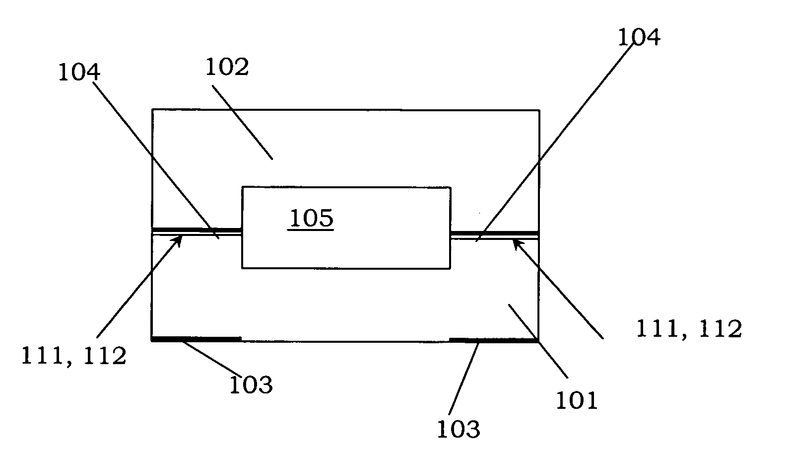
[0085] The first and second member 101, 102 of the third embodiment have been bonded directly onto each other, at opposite bonding surfaces 111, 112, using direct-bonding. The resulting bond has been improved using a further anodic bonding of the first and second member 101, 102. As has been shown, an outer surface of the first member 101 has been provided with electrodes 103. The bonding surface 112 of the second member 102 has also been provided with electrodes 104, which extend between the first and second member 101102 after the direct-bonding of the members 101, 102. The electrodes 103, 104 are used in the anodic bonding. The anodic bonding is achieved by applying a potential difference between the electrodes 103, 104 to drive an ion current therebetween for forming an anodic bond at the bonding surfaces 111, 112, similar to the embodiment shown in FIG. 6.
[0086] While specific embodiments of the invention have been described above, it will be appreciated that the invention may ...
PUM
| Property | Measurement | Unit |
|---|---|---|
| specific resistivity | aaaaa | aaaaa |
| specific resistivity | aaaaa | aaaaa |
| specific resistivity | aaaaa | aaaaa |
Abstract
Description
Claims
Application Information
 - R&D
- Intellectual Property
- Life Sciences
- Materials
- Tech Scout
- Unparalleled Data Quality
- Higher Quality Content
- 60% Fewer Hallucinations
Browse by: Latest US Patents, China's latest patents, Technical Efficacy Thesaurus, Application Domain, Technology Topic, Popular Technical Reports.
© 2025 PatSnap. All rights reserved.Legal|Privacy policy|Modern Slavery Act Transparency Statement|Sitemap|About US| Contact US: help@patsnap.com


