
Method and architecture for dual-mode linear and saturated power amplifier operation

a power amplifier and linear technology, applied in the field of wireless communications technologies, can solve the problems of user's own data transmission being corrupted, affecting the transmission of other gsm users, and rf signal spilling out of the allowable transmission spectrum,

Inactive Publication Date: 2005-06-23
QORVO US INC
View PDF99 Cites 61 Cited by
  • Summary
  • Abstract
  • Description
  • Claims
  • Application Information

AI Technical Summary

Benefits of technology

[0031] According to an embodiment of the invention, the leading and trailing bits of the EDGE bit stream (which are non-data-carrying bits) can be replaced with bits having a constant logic state. The single tone sine wave generated from the constant bit stream can then be amplified during the ramp up and ramp down portions of the EDGE burst output signal without generating spurious spectral components (i.e., without causing spectral splatter).
[0032] To generate the data burst portion of an EDGE burst output signal, the collector voltage(s) of the power transistors in the PA are raised above a threshold voltage, thereby allowing the PA to operate in linear mode. The non-constant envelope EDGE data burst can then be generated by the combination of the VGA and PA. Since the PA is operating in linear mode, the EDGE data burst can be generated without data corruption. Furthermore, since the PA can provides the bulk of the gain required for the ramp up portion of the EDGE signal, the VGA need only provide enough gain to meet the PCL requirements (typically about 26 dB). The invention therefore eliminates the need for the high-gain VGA used in conventional EDGE transmitters. Furthermore, the use of collector voltage to control ramp transition levels in both GSM and EDGE modes is synergistic, since the well-known collector control techniques used in conventional GSM modes can be applied to EDGE operation.

Problems solved by technology

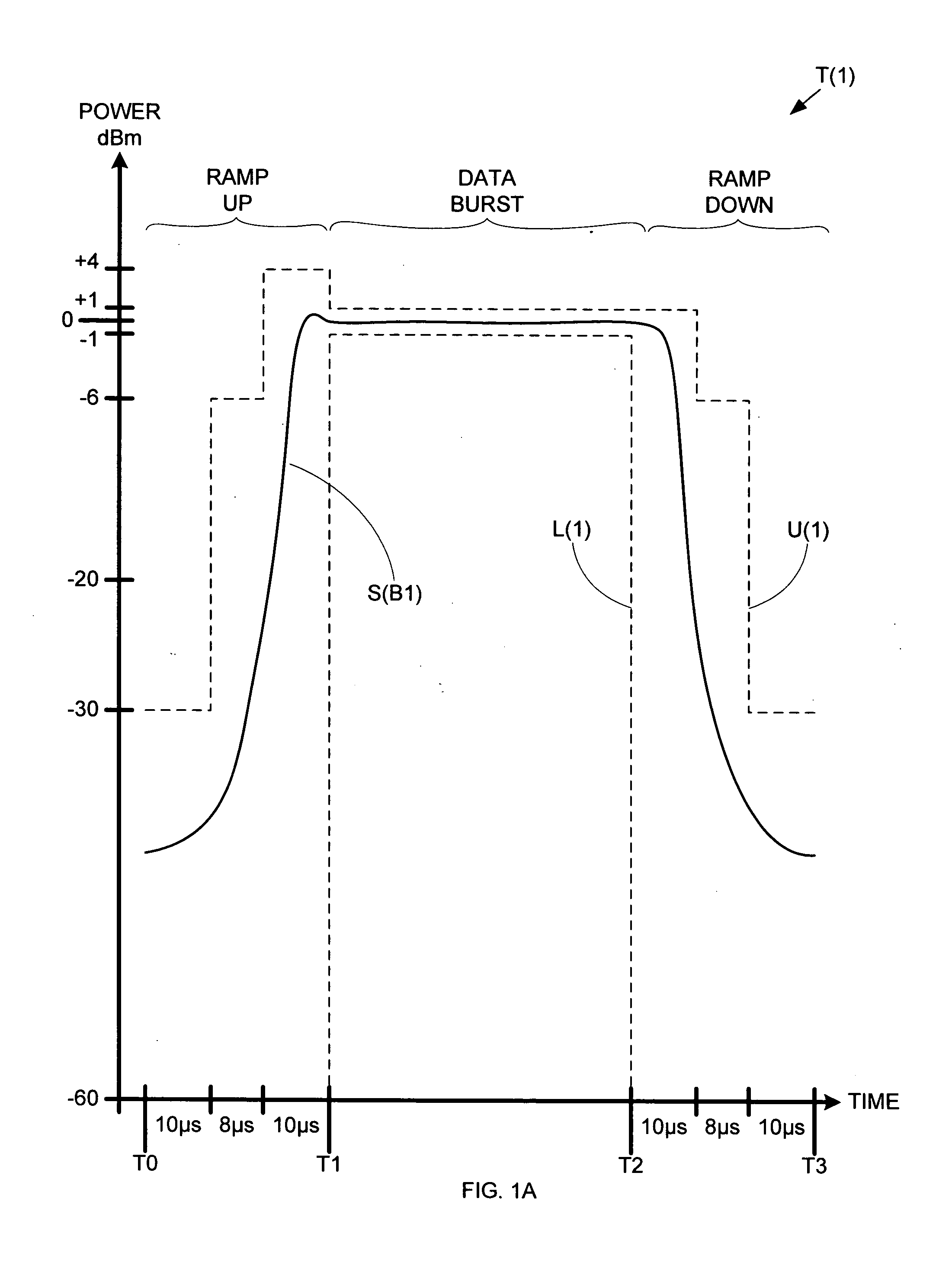
If a burst output signal turns on (i.e., ramps up) or turns off (i.e., ramps down) too quickly, the RF signal can spill out of the allowable transmission spectrum (“signal splatter”) and interfere with the transmissions of other GSM users.
However, if the burst output signal turns on or turns off too slowly, the user's own data transmission may be corrupted.
However, the relatively low data rate of GSM is a limiting factor as mobile communications move beyond simple voice transmissions into more bandwidth-intensive transmissions (e.g., images and video).
However, the improved data efficiency of EDGE comes with added modulation complexity.
Applying only saturated mode amplification in this situation (high gain applied to a non-constant envelope signal) can generate unwanted spectral components (spectral splatter) in burst output signal S(B2), thereby resulting in a non-compliant EDGE signal (i.e., a signal that does not meet the EDGE spectral mask specifications shown in FIG. 2C).
Unfortunately, providing the degree of control over VGA 230 required to generate an EDGE compliant burst output signal S(B2) can be very difficult due to the indirect nature of the control.
However, providing the precise output control required to maintain compliance with the EDGE timing mask can be difficult to provide using only VGA control, since the magnitude of the output signal (i.e., burst output signal S(B2)) is dependant on the level of modulated signal S(M2), the gain of VGA 230, and the gain of PA 240.
In addition, PA 240 is subject to gain expansion, which makes precise gain control even more difficult.
Having such a wide dynamic range would typically require a significant number of amplifier stages, which creates greater opportunity for accuracy degradation through process variations (during manufacturing) and temperature variations (during operation).
A VGA that provides accurate linear response across such a wide dynamic range can be difficult to realize cost effectively.

Method used


Image

  • Method and architecture for dual-mode linear and saturated power amplifier operation
  • Method and architecture for dual-mode linear and saturated power amplifier operation
  • Method and architecture for dual-mode linear and saturated power amplifier operation

Examples


Embodiment Construction

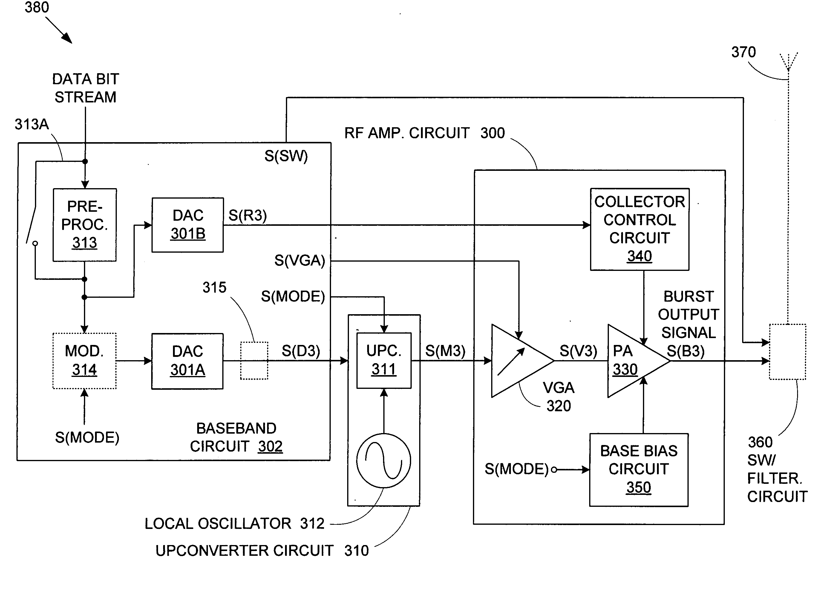
[0043]FIG. 3 shows a schematic diagram of a transmitter 380 (such as a cellular telephone) that includes a RF amplifier circuit300 in accordance with an embodiment of the invention. In addition to RF amplifier circuit 300, transmitter 380 includes a baseband circuit 302, an upconverter circuit 310, an optional switching / filtering circuit 360, and an antenna 370.

[0044] Note that according to an embodiment of the invention, baseband circuit 302 can be incorporated into a separate baseband chip. According to various other embodiments of the invention, upconverter circuit 310 and RF amplifier circuit 300 can likewise be incorporated into separate chips. According to other embodiments of the invention, all or various sub-combinations of baseband circuit 302, upconverter circuit 310, and RF amplifier circuit 300 can be incorporated into a single chip.

[0045] During operation of transmitter 380, a data bit stream for a GSM or EDGE transmission is provided to baseband circuit 302. In respo...


PUM


Abstract

An RF transmitter provides both GSM and EDGE capability by implementing collector voltage control over the power transistor(s) in a power amplifier. During EDGE mode, linear base-biasing a power amplifier (PA) allows collector control to provide either saturated mode PA operation (during ramp up / ramp down) or linear mode PA operation (during data burst). Collector control can therefore be used to provide the accurate ramp up and ramp down profiles required for both GSM and EDGE burst output signals, and can also be used to set the level of the constant envelope data burst of a GSM burst output signal, while linear mode PA operation can provide the non-constant envelope EDGE data burst. A variable gain amplifier is used to adjust the input signal to the power amplifier such that the desired transmission level is achieved.

Description

BACKGROUND OF THE INVENTION [0001] 1. Field of the Invention [0002] The invention relates to wireless communications technologies, and in particular to a system and method for providing an efficient GSM-EDGE dual-mode transmitter. [0003] 2. Related Art [0004] Communications using the global system for mobile telecommunication (GSM, see 3GPP(™) Technical Specification 45.005 v5.5.0 (August 2002)) system are transmitted within two predetermined transmission spectra—890-915 MHz in the uplink direction (i.e., from the mobile station to the base station) and 935-960 MHz in the downlink direction (i.e., from the base station to the mobile station). To make efficient use of these transmission spectra, bandwidth allocation to individual users is provided via frequency division multiple access (FDMA) and time division multiple access (TDMA). [0005] FDMA is used to divide the transmission spectra into multiple carrier frequencies of 200 kHz. Each carrier frequency is then divided into 4.615 m...

Claims


Application Information

Patent Timeline
IPC IPC(8): H03G3/30H04BH04B7/005H04K1/02
CPCH03F1/0261H03G3/3047H04W52/38H04W52/52H04B2001/045H03F3/24H03F1/02
Inventor ZHANG, ANDREWAPEL, THOMAS R.STEPHENS, CHRISTOPHER R.
Owner QORVO US INC
Learn More