Solid oxide fuel cell sealant comprising glass matrix and ceramic fiber and method of manufacturing the same

a technology of solid oxide fuel cell and glass matrix, which is applied in the manufacture of cell components, coupling device connections, and final product products, etc., can solve the problems of reducing the effective space of the end cell, and even terminating the fuel cell operation. , to achieve the effect of preventing or minimizing the viscosity flow of glass matrix

Inactive Publication Date: 2005-07-07
HYUNDAI MOTOR CO LTD +1
View PDF3 Cites 55 Cited by
  • Summary
  • Abstract
  • Description
  • Claims
  • Application Information

AI Technical Summary

Benefits of technology

[0012] In another aspect, the invention provides a method for manufacturing a solid oxide fuel cell sealant, wherein the produced product can efficiently prevent or minimize viscous flow of glass matrix, precisely locate the stack of fuel cell on the region to be sealed, and maintain uniform sealing under various changes of the size of the fuel cell stack.

Problems solved by technology

However, when that glass is used alone, glass sealant may be damaged due to brittle breaks resulting from rapid cooling or repeated heating / cooling.
In addition, in the event that glass is prepared in the form of a sealant paste, replacement can be difficult when required due to the damage on the end cell or a sealant.
In prior systems, when viscous flow of glass cannot be restricted within a certain geometrical range, the viscous glass penetrates within the stack thereby reducing the effective space of the end cell and even terminating fuel cell operation.
Meanwhile, when mica is used as a sealant it often results in having a poor sealing ability due to its coarse surface thus requiring an increased level of compressed load for a better sealing effect.
However, the manufacturing process is complex and producing the sealant in a multi-layered structure also can be difficult.
Current technologies in structure planning and manufacturing are far behind in meeting requirements for resolving those objectives.

Method used


Image

  • Solid oxide fuel cell sealant comprising glass matrix and ceramic fiber and method of manufacturing the same
  • Solid oxide fuel cell sealant comprising glass matrix and ceramic fiber and method of manufacturing the same
  • Solid oxide fuel cell sealant comprising glass matrix and ceramic fiber and method of manufacturing the same

Examples


examples 1-5

Manufacture of Glass Matrix for Sealant

[0049] A glass to be used as a component for preparing a glass / ceramic fiber sealant for tight sealing at high temperature by using BaO—Al2O3—SiO2 type glass (“BAS”-type glass hereinafter) was manufactured and the physical properties of thus prepared glass were analyzed. 70 g of the mixed material prepared according to the following Table 1, 35 g of isopropyl alcohol along with 20 zirconia balls with a diameter of 10 mm were added into a 100 cc polypropylene bottle and mixed homogeneously via wet process using a rotational ball mill. The mixed material was then completely dried under vacuum at 80° C. for 5 hr, remelted at 1,450° C. for 2 hr by using Siliconite or Super Kantal electric furnace, and then rapidly cooled down with distilled water to produce the primary glass. The thus prepared glass was pulverized via alumina induction to improve the homogeneity of the above primary glass, remelted at 1,450° C. for 2 hr, poured into a stainless st...

experimental example 1

Comparison of Glass to be Used for Manufacturing Sealants

[0051] The basic properties of glass were measured: softening point (Ts), glass transition temperature (Tg) and coefficient of thermal expansion (CTE) were measured by using a heat expansion coefficient measuring device (dilatimeter, DIL 402C, Netzsch). Cooled mother glass was processed by using a diamond isomer (Buehler) into the one with 5×5×10 mm and coefficients of linear thermal expansion were measured. The coefficients of linear thermal expansion of mother glass prepared according to various compositions were measured by first installing specimens to be measured along with standard specimen on a push rod, then heating them in an ambient atmosphere under pressure of 15 cN at the rate of 10° C. / min until they reach 1,000° C., thereby sensing the minute difference in thermal expansion between the standard specimen and each specimen to be measured using the push rod. The density (ρ) of each of the glass manufactured were me...

examples 5-9

Manufacture of a Gasket Using the Glass / Ceramic Fiber Sealant

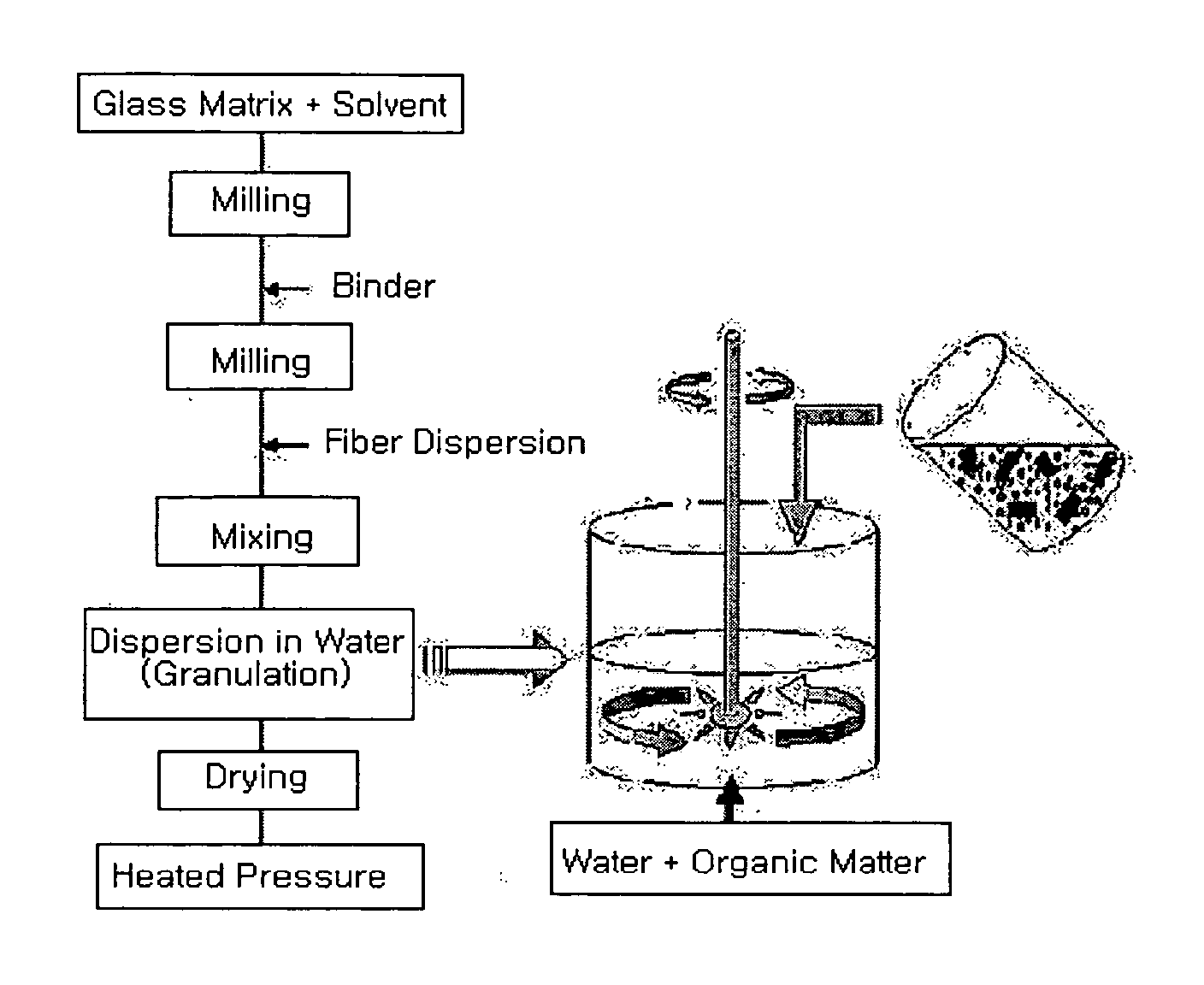
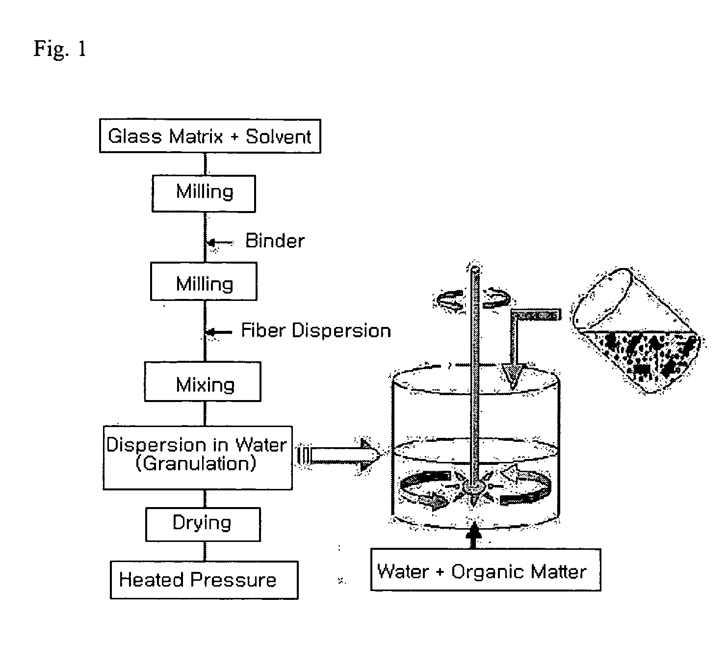
[0053] The “BAS”-type glass prepared in example 3 was pulverized to the size of 1 μm by using a planetary mill (350 rpm, 20 min), a mixture comprising the resulting pulverized glass the compositions of which are shown in the following Table 4, alumina silicate fiber (Al2O3:SiO2=1:1) and 2 wt % of starch solution were mixed in a container for 30 min to form a slurry. The slurry mixture was poured into a forming mold, pressed under 150 kg / cm3 for 10 min to produce a glass / ceramic fiber gasket forming body, and then dried at 80° C. for 12 hr to manufacture a glass / ceramic fiber gasket. The shrinkage rate, apparent density, and apparent porosity of thus manufactured glass / ceramic fiber gasket were respectively measured by using distilled water based on Archimedes' Principle and the results are shown in the following Table 4.

TABLE 4GlassCeramicApparentApparent(Vol.Fiber1)ShrinkageDensityPorosityClassification%)(Vol. %)Rate (...


PUM

PropertyMeasurementUnit
aspect ratioaaaaaaaaaa
porosityaaaaaaaaaa
temperatureaaaaaaaaaa

Abstract

Sealant compositions particularly suitable for solid oxide fuel cell sealant are provided and preferably comprise glass matrix and ceramic fiber, wherein glass matrix and ceramic fiber are mixed in an volume ratio of 25:75-75:25 in the sealant, and the ceramic fibers are preferably uniformly dispersed in the sealant to exhibit an orientation. Methods to manufacture the sealant compositions also are provided. Particularly preferred sealant compositions of the invention can efficiently avoid undesired viscous flow of glass matrix, precisely locate the stack of fuel cell on the region to be sealed, and maintain uniform sealing ability under various changes in size of the fuel cell stack.

Description

CROSS REFERENCE TO RELATED APPLICATIONS [0001] This application is based on, and claims priority from Korean Application No. 2004-0000278, filed on Jan. 5, 2004, the disclosure of which is hereby incorporated by reference. TECHNICAL FIELD OF THE INVENTION [0002] This invention relates to a solid oxide fuel cell sealant comprising glass matrix and ceramic fiber, and a method for manufacturing the solid oxide fuel cell sealant. BACKGROUND OF THE INVENTION [0003] In a flat solid oxide fuel cell, a sealant positioned between a solid electrolyte and a jointer generally acts as a sealing adhesive to prevent mixing between a hydrogen fuel gas, which is directly supplied to a cathode, and an air gas, which is in contact with an anode. In particular, the sealant should be able to prevent gas leakage under reducing and oxidizing atmospheres at high temperature. The sealant also should provide structural stability without reactivity at each respective interface. [0004] Conventional sealants in...

Claims


Application Information

Patent Timeline
Patent Type & Authority Applications(United States)
IPC IPC(8): C03C8/24C03C14/00H01M8/02H01M8/12
CPCC03C8/24C03C14/002Y02E60/50Y02E60/522H01M8/0282Y02P70/50H01R13/70H01R25/003H01H43/24
Inventor KO, HAENG JINLEE, HAE WEONLEE, JAE CHUNLEE, JONG HOSONG, HUE SUPKIM, JOO SUNNOH, TAE WOOK
Owner HYUNDAI MOTOR CO LTD
Why Eureka
Try Eureka