Protective coating composition

a coating composition and coating technology, applied in the direction of coatings, plasma techniques, material granulation, etc., can solve the problems of inability or difficulty to achieve processes, limited adoption of plasma technology, low or moderate throughput, etc., to improve compatibility, improve the effect of reducing the number of oxidation and/or moisture, and improving the barrier properties and control of release properties

Inactive Publication Date: 2005-07-21
DOW CORNING CORP
View PDF46 Cites 37 Cited by
  • Summary
  • Abstract
  • Description
  • Claims
  • Application Information

AI Technical Summary

Benefits of technology

[0047] An advantage of the present invention over the prior art is that both liquid and solid atomized coating-forming materials may be used to form coatings on powdered substrates, due to the method of the present invention taking place under conditions of atmospheric pressure. Furthermore the coating-forming materials can be introduced into the plasma discharge or resulting stream in the absence of a carrier gas, i.e. they can be introduced directly by, for example, direct injection, whereby the coating forming materials are injected directly into the plasma.
[0048] As mentioned above, the present inventors have found particular utility of the present invention for forming silica- and siloxane-based coatings on powdered substrates using silicon-containing materials. Under oxidising conditions, e.g. an oxygen containing atmosphere, silica-like coatings can be formed on the powdered substrate surface from atomised silicon-containing materials, whereas under non-oxidizing conditions, a siloxane polymer, e.g. a linear, branched or resinous siloxane polymer, can be formed on the powdered substrate surface from atomization of a silicon-containing monomer. A siloxane-organic copolymer can be formed on the powdered substrate surface by use of a mixture of organic and silicon-containing monomers. However, the present invention is also useful for forming an organic coating on a powdered substrate, for example a polyacrylic acid or perfluoro-organic coating.
[0049] Powdered substrates coated by the method of the present invention may have various utilities. For example, a silica based coating may give encapsulation through enhanced barrier (oxygen and / or moisture) properties and controlled release properties to an organic particle such as a fragrance, flavour, pharmaceutical or dyestuff. Improved compatibility could be achieved for metal or metal oxide powders used as reinforcing or property modifying fillers in rubbers and plastics. Improved compatibility may also be utilised for dispersions such as dyestuffs / pigments, antioxidants and UV stabilisers in polymer materials and also formulated products such as paints and cosmetics. Powder processing may be improved by enhancing characteristics such as flow, compatibility and electrostatic properties. Specific functionalities may be added to catalysts and catalyst support to enhance or control reactivity. Also surface and pore properties of powders used as separation media or as support for separation media may be controlled.
[0050] In one embodiment of the invention a statically electric charged porous plate or a vibrating sieve may be placed in line with the exit of the powdered substrate from the plasma region to collect the resulting powdered substrate.FIGS.
[0051] The present invention will now be described further on the basis of the following examples and drawings in which:
[0052]FIG. 1 shows a plan view of an embodiment of the invention where the powdered substrate is transported through the plasma region by gravity.

Problems solved by technology

Furthermore, their high energy content allows them to achieve processes which are impossible or difficult through the other states of matter, such as by liquid or gas processing.
However, adoption of plasma technology has been limited by a major constraint on most industrial plasma systems, namely, their need to operate at low pressure.
Throughput is low or moderate and the need for vacuum adds capital and running costs.
However, despite their high manufacturability, these systems have failed to penetrate the market or be taken up by industry to anything like the same extent as the lower pressure, bath-processing-only plasma type.
The reason is that corona / flame systems have significant limitations.
The treatment is often non-uniform and the corona process is incompatible with thick webs or 3D webs while the flame process is incompatible with heat sensitive powdered substrates.
All of the aforementioned prior art relate to the activation of the powdered substrate or applications of coatings using gas phase precursors and typically the results suggest low deposition rates and require high residence times to obtain a sufficiently coated surface.

Method used


Image

  • Protective coating composition
  • Protective coating composition
  • Protective coating composition

Examples


example 1

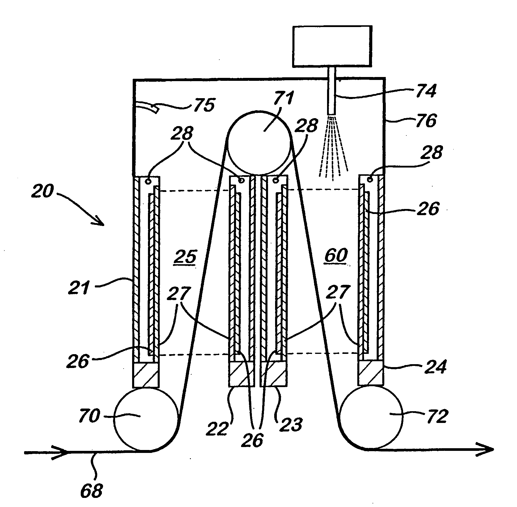
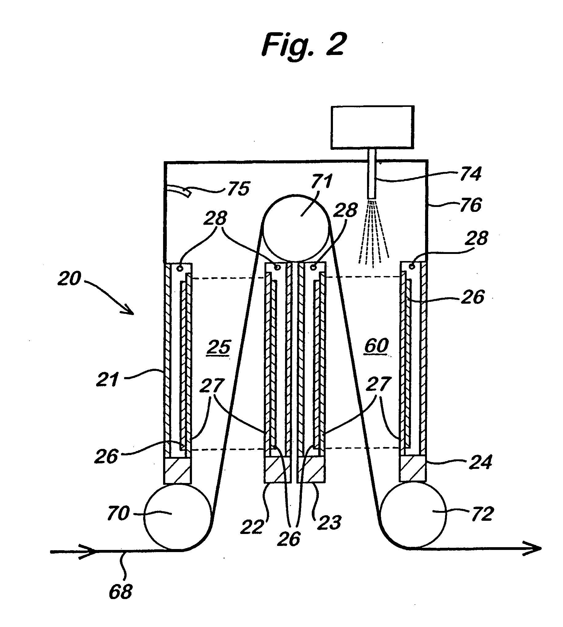
[0058] The following example describes the plasma treatment of a rice hull ash sold under the name Ricesil™ (Rice Chemistry Inc. of Stuttgart, Ariz., USA), which is a biogenic amorphous silica, in accordance with the embodiment described in FIG. 2. In this example the distance between the glass dielectric plates attached to the two electrodes was 6 mm and the surface area of each electrode was (10 cm×50 cm). The process gas used was helium. An atmospheric pressure glow discharge was generated by applying RF power of 1 W / cm2 to two electrodes with a frequency of 29 kHz. The operating temperature was below 40° C. The powdered substrate was passed through both the first and second plasma zones using a reel-to-reel mechanism of the type described in FIG. 2 with a guide means being utilised to assist in the transport of the powdered substrate out of the first and into the second plasma regions. The speed of the powdered substrate passing through both plasma zones was 1 m min−1. The rice ...


PUM

PropertyMeasurementUnit
pressureaaaaaaaaaa
drop sizeaaaaaaaaaa
drop sizeaaaaaaaaaa

Abstract

A method of forming a coating on a powdered substrate, which method comprises introducing an atomized liquid and / or solid coating forming material and separately transporting a powdered substrate to be coated into an atmospheric plasma discharge and / or an ionized gas stream resulting therefrom, and exposing the powdered substrate to the atomized liquid and / or solid coating forming material.

Description

CROSS-REFERENCE TO RELATED APPLICATIONS [0001] This present application is a US national stage filing under 35 USC 371 and claims priority from PCT Application No. PCT / EP03 / 04346 entitled “PROTECTIVE COATING COMPOSITON” filed on 8 Apr. 2003, currently pending, which claims priority from Great Britain Patent Applications No. 0208263.4 and 0208261.8 entitled “PROTECTIVE COATING COMPOSITION”, both filed on 10 Apr. 2002.FIELD OF INVENTION [0002] The present application describes a process for coating powdered particles using atmospheric pressure plasma techniques. BACKGROUND OF THE INVENTION [0003] When matter is continually supplied with energy, its temperature increases and it typically transforms from a solid to a liquid and, then, to a gaseous state. Continuing to supply energy causes the system to undergo yet a further change of state in which neutral atoms or molecules of the gas are broken up by energetic collisions to produce negatively charged electrons, positive or negatively ...

Claims


Application Information

Patent Timeline
Patent Type & Authority Applications(United States)
IPC IPC(8): B01J2/00C08K9/00C08L101/00C23C4/12H05H1/24
CPCC23C4/121H05H1/24C23C4/127H05H1/46C23C4/123C23C4/134H05H1/2431H05H1/4697H01J37/32
Inventor GOODWIN, ANDREW JAMESLEADLEY, STUARTRYAN, SEAMUS PAUL
Owner DOW CORNING CORP
Why Eureka
Try Eureka