
Semiconductor-producing apparatus

Inactive Publication Date: 2005-07-28
SUMITOMO ELECTRIC IND LTD
View PDF2 Cites 7 Cited by
  • Summary
  • Abstract
  • Description
  • Claims
  • Application Information

AI Technical Summary

Benefits of technology

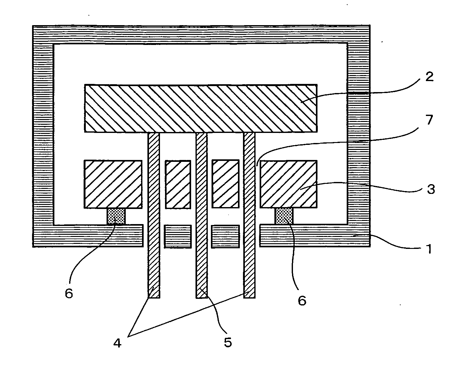
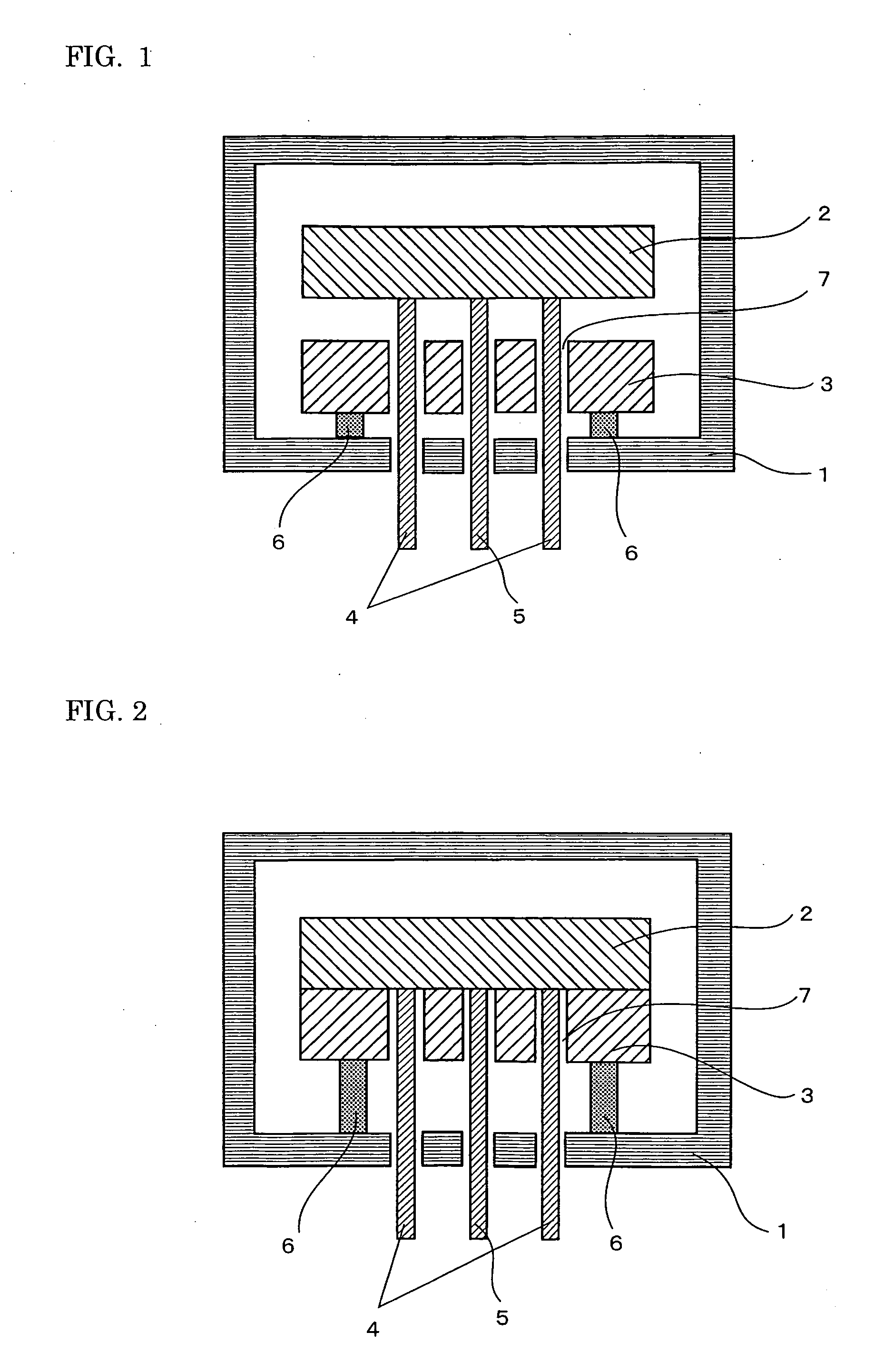
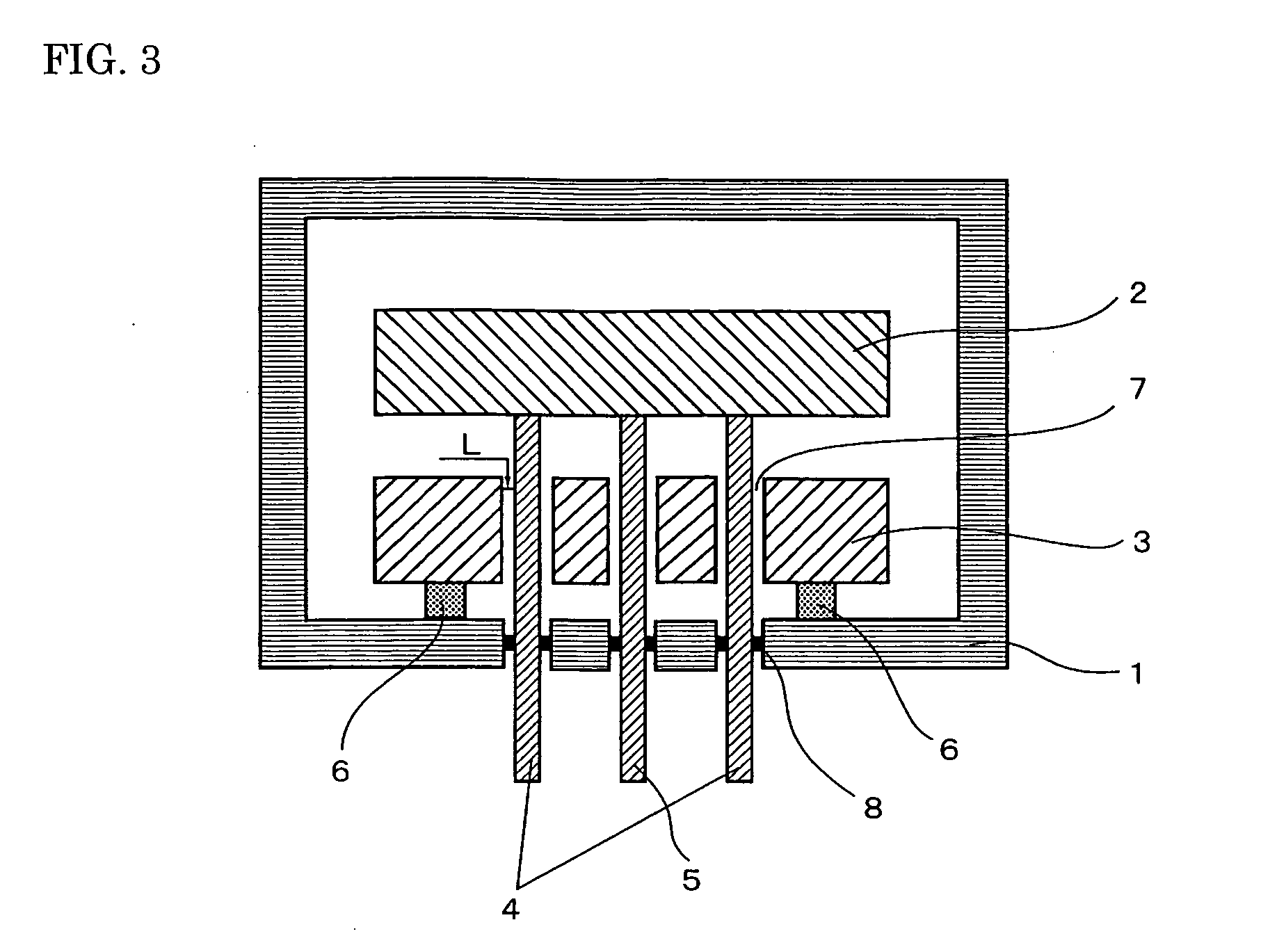
[0010] In view of the above-described problems, an object of the present invention is to offer a semiconductor-producing apparatus in which not only is the cooling rate of the heater increased but also the uniformity in the temperature distribution of the heater is increased. Such a semiconductor-producing apparatus can be used in a wider range of application.
[0012] The cooling block may have a distance of at least 0.1 mm from the inner surface of the or each through hole to the penetrating object. In this case, the uniformity of the temperature distribution of the heater is further increased.
[0015] The present invention enables the production of a semiconductor-producing apparatus provided with a heater that has not only a dramatically increased cooling rate, which is achieved by bringing the cooling block into contact with the heater when the heater is cooled, but also an excellent uniformity in temperature distribution. Consequently, when the semiconductor-producing apparatus of the present invention is applied to the following various semiconductor-producing apparatuses, the apparatuses can have a sufficient temperature distribution: an etching device, a sputtering device, a plasma CVD unit, a reduced-pressure plasma CVD unit, a metal CVD unit, an insulating-film CVD unit, a low-dielectric-constant-film CVD unit, an MOCVD unit, a degasifier, an ion implanter, a coater-developer, and so on.

Problems solved by technology

However, it turned out that the provision of the cooling block causes the temperature distribution of the heater to be nonuniform.
Depending on the application, the nonuniformity in the temperature distribution of the heater poses a problem.
As a result, the technique proposed in the foregoing Tokukai 2004-014655 has been limited to the application that does not require high uniformity in the temperature distribution of the heater.

Method used


Image

  • Semiconductor-producing apparatus
  • Semiconductor-producing apparatus
  • Semiconductor-producing apparatus

Examples


example 1

[0069] An aluminum nitride sintered body was produced by the following process. First, 100 weight parts of aluminum nitride powder and 0.6 weight parts of yttrium stearate powder were mixed. Next, 10 weight parts of polyvinyl butyral as a binder and 5 weight parts of dibutyl phthalate as a solvent were mixed into the foregoing mixed powder. The resultant mixed material was processed by the spray-drying method to produce granules. The granules were press-formed and degreased in a nitrogen atmosphere at 700° C. The formed body was sintered in a nitrogen atmosphere at 1,850° C. to complete the process. The aluminum nitride powder used had an average particle diameter of 0.6 μm and a specific surface area of 3.4 m2 / g. The produced aluminum nitride sintered body was machined so as to have a diameter of 330 mm and a thickness of 15 mm.

[0070] A tungsten paste was produced by using 100 weight parts of tungsten powder having an average particle diameter of 2.0 μm, one weight part of Y2O3, f...

example 2

[0077] Five types of cooling blocks were prepared that were made of different materials as shown in Table II. They had a distance of 0.5 mm from the inner surface of the through hole of the cooling block to the penetrating object such as the electrode or thermocouple. The conditions other than the material of the cooling block, such as the heater and the coolant-flowing path, were the same as in Example 1. The temperature variation in the heater was measured at 400° C. and 200° C. The results are shown in Table II. The thermal conductivity of the material of the cooling block is also shown in Table II.

TABLE IIThermalconductivityNo.Material of cooling block(W / mK)ΔT1 (° C.)ΔT2 (° C.)8Nickel-chromium steel174.18.59Nickel steel302.45.010Pure iron752.44.911Cast aluminum1001.63.212Pure aluminum2001.53.1

[0078] As can be seen from Table II, when the thermal conductivity of the material of the cooling block was increased to 30 W / mK or more, the uniformity of the temperature distribution of...

example 3

[0079] Three types of heaters were produced with different materials through a method similar to that used in Example 1. They were made of aluminum oxide, silicon carbide, and silicon nitride. The heater made of aluminum nitride produced in Example 1 was also used in this example. That is, four types of heaters were used in total. The distance from the inner surface of the through hole of the cooling block to the penetrating object such as the electrode or thermocouple was 0.5 mm. The material of the cooling block was pure aluminum. As with Example 1, the temperature variation in the heater was measured at 400° C. and 200° C.

[0080] In addition, after the temperature of the heater was raised to 400° C. when measured by the thermocouple, the temperature, 400° C., was maintained for 30 minutes to achieve temperature stabilization. Then, the current feeding was stopped. The cooling block to which cooling water was fed was brought into contact with the heater to cool it to 50° C. The te...


PUM

PropertyMeasurementUnit
Distanceaaaaaaaaaa
Distanceaaaaaaaaaa
Temperatureaaaaaaaaaa

Abstract

A semiconductor-producing apparatus increases both the cooling rate of the heater and the uniformity in the temperature distribution of the heater. The semiconductor-producing apparatus of the present invention is provided with a heater for heat-treating a semiconductor wafer and a cooling block for cooling the heater. The cooling block is provided with at least one through hole for inserting a penetrating object. The distance from the inner surface of the or each through hole to the penetrating object is at most 50 mm. The cooling block is arranged such that it can both make contact with and separate from the heater's face opposite to the face for placing the wafer. The foregoing penetrating object is a current-feeding electrode for feeding current to the heater circuit, a temperature-measuring means, or the like.

Description

BACKGROUND OF THE INVENTION [0001] 1. Field of the Invention [0002] The present invention relates to a semiconductor-producing apparatus that is provided with a heater for heating a wafer placed on it to perform an intended treatment and with a cooling block for cooling the heater and that can be applied to the following apparatuses: an etching device, a sputtering device, a plasma CVD unit, a reduced-pressure plasma CVD unit, a metal CVD unit, an insulating-film CVD unit, a low-dielectric-constant-film (Low-K) CVD unit, an MOCVD unit, a degasifier, an ion implanter, a coater-developer, and so on. [0003] 2. Description of the Background Art [0004] As a usual practice, in the process for producing a semiconductor, a material to be treated such as a semiconductor substrate (wafer) is subjected to various treatments including film formation and etching. A semiconductor-producing apparatus for performing such treatments of a semiconductor substrate is provided with a ceramic heater for ...

Claims


Application Information

Patent Timeline
IPC IPC(8): C23C16/00H01L21/02C23C16/458C23C16/46H01L21/00
CPCC23C16/4586H01L21/67109C23C16/46
Inventor SHINMA, KENJINAKATA, HIROHIKONATSUHARA, MASUHIRO
Owner SUMITOMO ELECTRIC IND LTD
Learn More