Apparatus, method, and program for generating range-image-data

a range image and data technology, applied in the direction of distance measurement, radiation control devices, instruments, etc., can solve the problems of increased pmosfet, increased pmosfet, and difficulty in boosting the output power of a light emitting element such as a light emitting diode or a laser diode employed as a pulsed light source without sacrificing high speed, so as to achieve short distances and reduce the effect of pmosfet and the capacity of photo

Active Publication Date: 2005-07-28
DENSO CORP
View PDF1 Cites 78 Cited by
  • Summary
  • Abstract
  • Description
  • Claims
  • Application Information

AI Technical Summary

Benefits of technology

[0027] In this case, the shorter the distance (0−Tmax) to the object is, the shorter the period when the reflected or scattered light is received within the exposure period (Tsh3) is. Accordingly, even when receiving the light reflected or scattered by an object existing at a distance which is so short that a relatively high reception level can be obtained, it is difficult to saturate the output from the photoelectric conversion elements. Consequently, the capacity of the photoelectric conversion elements can be utilized to the maximum.
[0028] The longer the distance to the object is, the longer the period when the reflected or scattered light is received within the

Problems solved by technology

However, the output power of a light emitting element such as a light emitting diode or a laser diode employed as a pulsed light source is difficult to boost without sacrificing high speed due to such constraints as the effect of parasitic elements and the current capacity of the power MOSFET that drives the light emitting element.
Particularly, if the driver of the light emitting element includes a CMOS inverter, the rise time of the pulsed light, when charges are supplied via a PMOSFET, is even longer because the current driving capacity of a PMOSFET is low compared to an NMOSFET.
That is, as shown in FIG. 12B, the conventional apparatus has the problem in that a measurement of good accuracy cannot be car

Method used


Image

  • Apparatus, method, and program for generating range-image-data
  • Apparatus, method, and program for generating range-image-data
  • Apparatus, method, and program for generating range-image-data

Examples


first embodiment

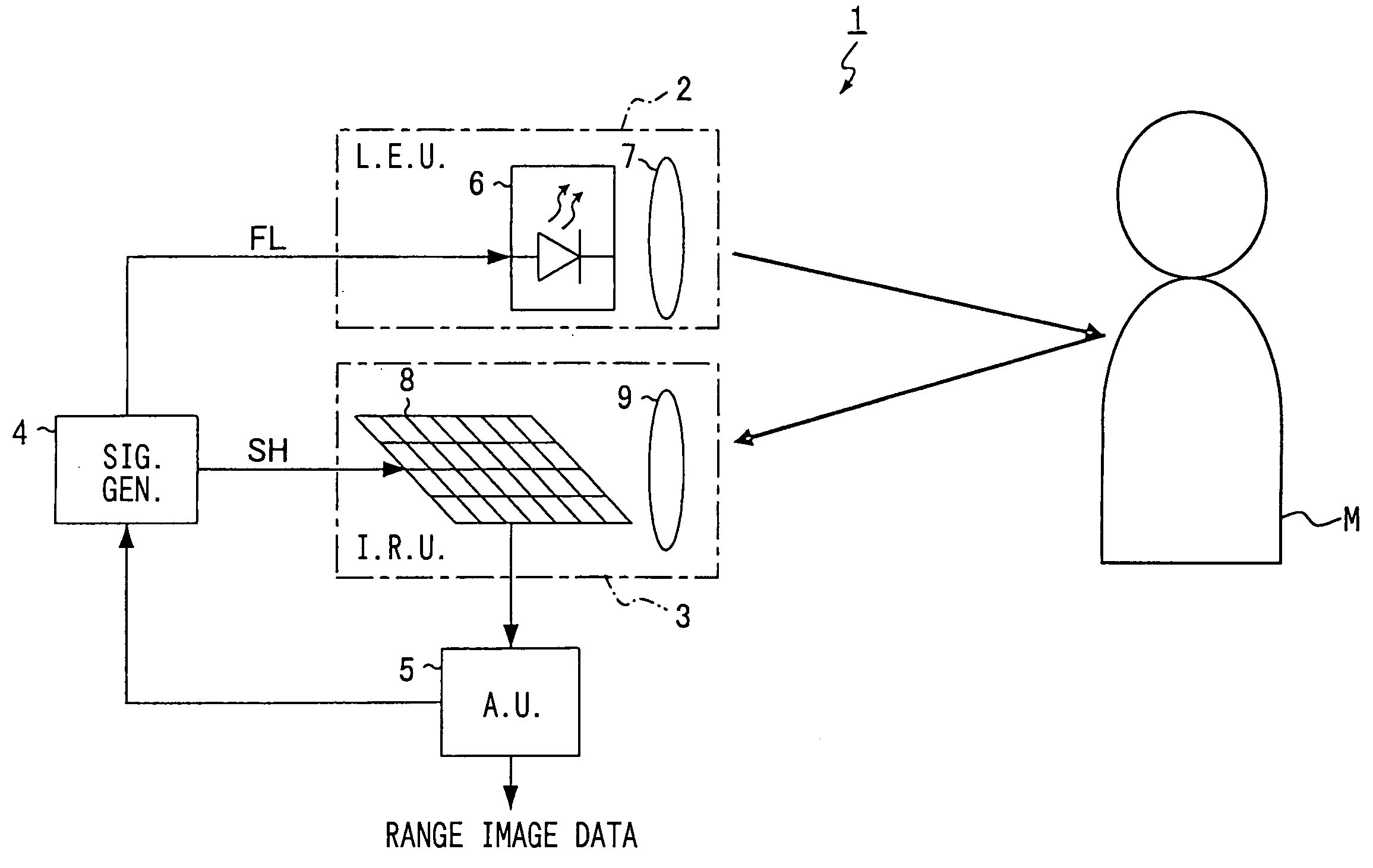
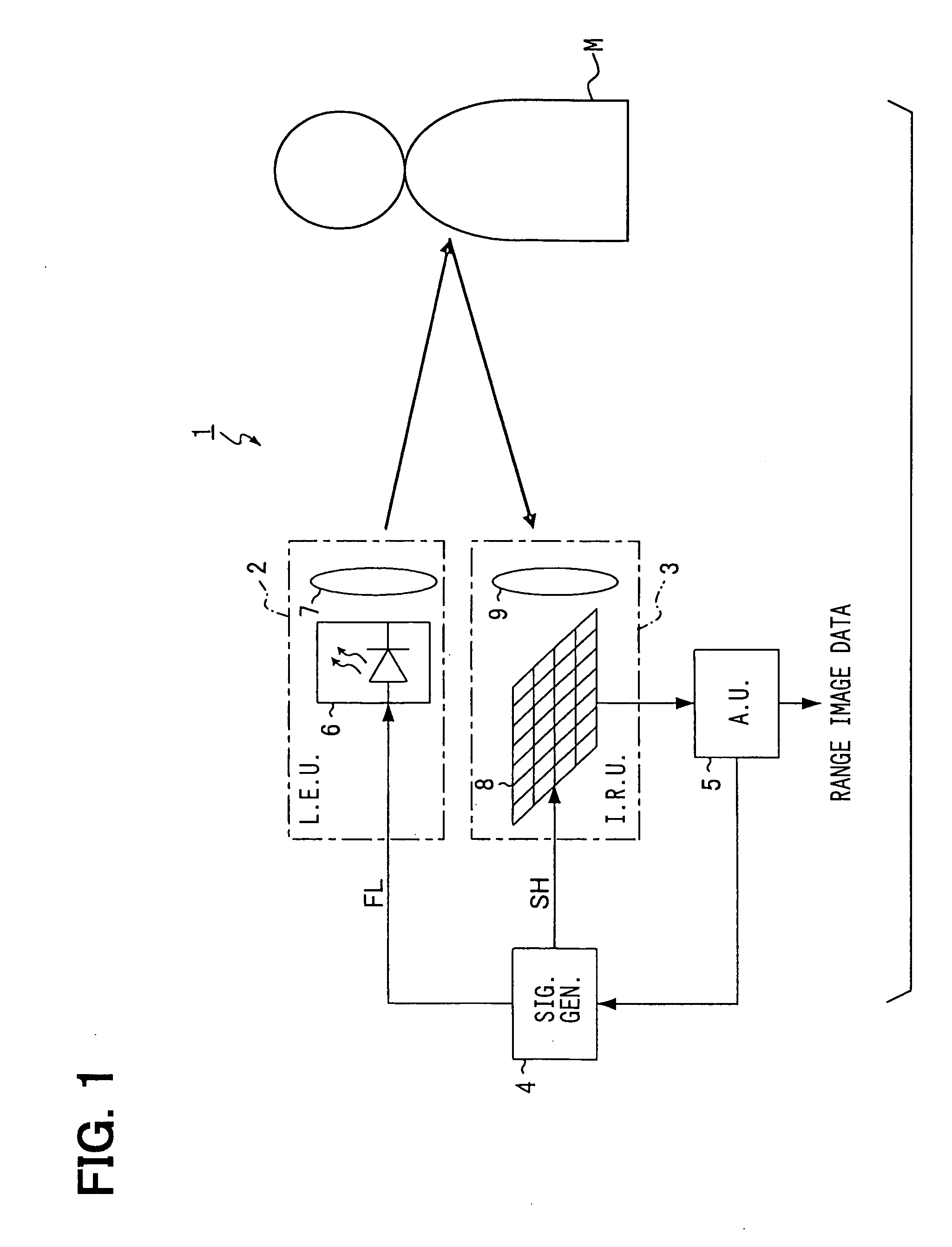
[0068]FIG. 1 is a block diagram showing the whole configuration of a range-image-data-generating apparatus 1 according to a first embodiment. The range-image-data-generating apparatus 1 includes a light emitting unit 2, an image receiving unit 3, a control signal generating unit 4, and an arithmetic unit 5. The light emitting unit 2 emits pulsed light in accordance with an emission signal FL. The image receiving unit 3 receives an image of the objects in a predetermined measuring area in accordance with an exposure signal SH. The control signal generating unit 4 generates emission signal FL and exposure signal SH. The arithmetic unit 5 so controls the control signal generating unit 4 as to generate range-image-data based on the image data from the image receiving unit 3.

[0069] The light emitting unit 2 is either a laser diode (LD) or a light emitting diode (LED), which emits near infrared rays. The light emitting unit 2 includes a light emitting element 6 and a diffusing lens 7. Th...

second embodiment

[0127] A second embodiment of the present invention will be described below.

[0128] This embodiment differs from the first embodiment in operation of the control signal generating unit 4 and a part of the processing executed by the arithmetic unit 5. Therefore, description will be provided below mainly of the operation of the control signal generating unit 4 of this embodiment and the different part of the processing executed by the arithmetic unit 5 of this embodiment.

[0129] Referring to FIG. 9, when the control signal generating unit 4 receives the first command from the arithmetic unit 5, the unit 4 generates an exposure signal SH having a pulse width (exposure time) Tsh1=Tmax×N, where N is an integer larger than one (the first step in FIG. 9). When the control signal generating unit 4 receives the second or third command from the arithmetic unit 5, the unit 4 operates in the same manner as in the first embodiment (the second or third step in FIG. 9). In FIG. 9, Tsh2=Tsh3=Tmax. ...

third embodiment

[0136] A third embodiment of the present invention will be described below.

[0137] This embodiment differs from the first embodiment in only part of the range-image-data generation. Therefore, mainly the different part will be described.

[0138] The range-image-data generation in this embodiment involves executing Step S160 after repeating Steps S110-S150 m times. The pixel values V4 of reference image data calculated m times at Step S140 are accumulated so that an accumulated value VR4 is obtained. The pixel values V5 of intensity image data calculated m times at Step S150 are accumulated so that an accumulated value VR5 is obtained. Step S160 is to calculate the ratio between the accumulated values VR4 and VR5 so as to find a pixel value VR (VR5 / VR4) of range-image-data.

[0139] The range-image-data-generating apparatus 1 of this embodiment carries out the accumulation while eliminating the noise component V1 due to the background light and the sensor operation. This improves the se...


PUM


Abstract

First image data including a first pixel value according to the intensity of background light is obtained by means of only exposure. Second image data including a second pixel value according to the intensity of the light reflected or scattered by an object is obtained by so controlling light emission and exposure as to receive part of the reflected or scattered light over the whole exposure period. The part of the reflected or scattered light corresponds to the flat period of emitted pulsed light. Third image data including a third pixel value according to the distance to the object is obtained by so controlling light emission and exposure as to receive the part of the reflected or scattered light for a time according to the distance. The first pixel value is subtracted from each of the second and third pixel values so that the influence of the background light can be excluded. The ratio between the subtraction results is calculated so that the influences of factors that vary the intensity of the reflected or scattered light can be cancelled.

Description

CROSS REFERENCE TO RELATED APPLICATION [0001] This application is based upon, claims the benefit of priority of, and incorporates by reference the contents of Japanese Patent Application No. 2004-20414 filed on Jan. 28, 2004. FIELD OF THE INVENTION [0002] The present invention relates to an apparatus, a method, and a program for generating range-image-data using pulsed light. BACKGROUND OF THE INVENTION [0003] An apparatus that emits pulsed light, receives light reflected or scattered from an object located in a preset measuring range by means of a photosensor having a plurality of pixels, and generates range images from the output from the photosensor is known. (for example, refer to Published Japanese translation No. 2002-500367 of PCT application). [0004] A range image represents the distance to a photographed object by image gradations (pixel values). The use of a range image makes it possible to measure at a time the distances to a plurality of objects located in a wide range. ...

Claims


Application Information

Patent Timeline
IPC IPC(8): G01B11/24G01C3/08G01S7/4863G01S7/487G01S17/04G01S17/88G01S17/894H01L27/146
CPCG01C3/08G01S17/026G01S17/88G01S7/4863H01L27/146G01S7/4876G01S17/89G01S17/04G01S17/894
Inventor SUZUKI, YOUSUKEYAMADA, HITOSHISUGAWARA, RYOICHISANO, NAOKI
Owner DENSO CORP
Why Eureka
Try Eureka