Monolithic wafer-scale waveguide-laser

a waveguide and monolithic technology, applied in the direction of laser details, active medium materials, active medium shape and construction, etc., can solve the problems of increasing labor and cost in the manufacturing process, exposing the optical fiber to a danger of scratching the fiber cladding, and reducing the coupling

Inactive Publication Date: 2005-08-04
COHERENT INC
View PDF22 Cites 16 Cited by
  • Summary
  • Abstract
  • Description
  • Claims
  • Application Information

AI Technical Summary

Benefits of technology

[0018] A plurality of optical pump sources are positioned about the side walls of the structure. Preferably, the optical pump sources are semico

Problems solved by technology

Given this relatively small diameter, the optical fiber is exposed to a danger of scratching the fiber cladding during handling.
This can make winding and spooling the optical fiber a very tedious operation.
This requires the use of discrete lenses (or mirrors) to efficiently couple the pump laser output energy into the fiber laser cavity, thereby adding labor and cost to the manufacturing process.
It is difficult (if not impossible) to find a binding matrix that satisfies all of these requirements.
Given the small diameter of such optical fiber and the danger of scratching the fiber cladding or fracturing the fiber during ha

Method used


Image

  • Monolithic wafer-scale waveguide-laser
  • Monolithic wafer-scale waveguide-laser
  • Monolithic wafer-scale waveguide-laser

Examples


Embodiment Construction

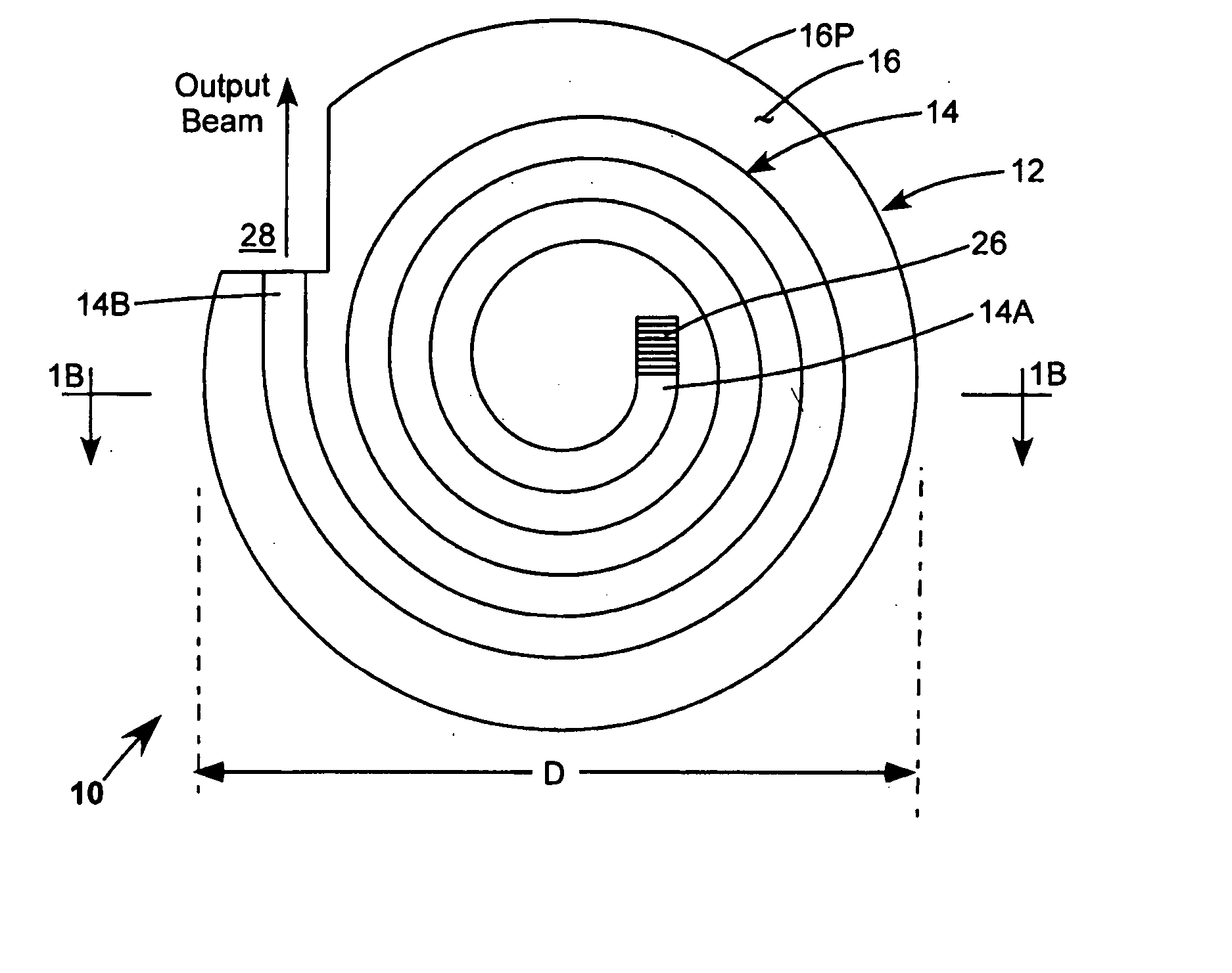
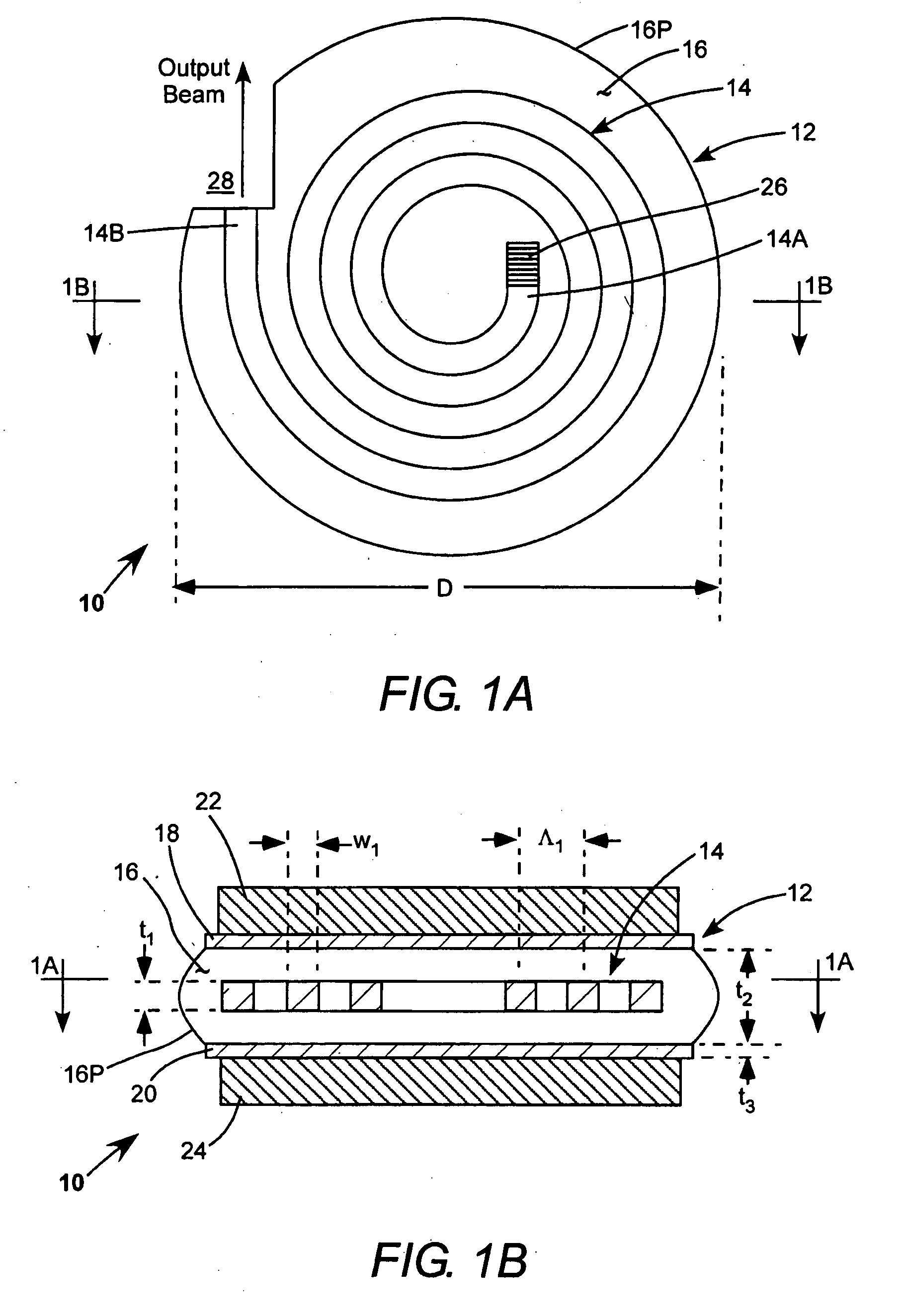
[0025] Referring now to the drawings, wherein like features are designated by like reference numerals, FIG. 1A and FIG. 1B schematically illustrate a preferred embodiment 10 of a monolithic, wafer-scale waveguide-laser in accordance with the present invention. Laser 10 includes a wafer body 12, preferably disc-shaped and having a diameter (D). The wafer body includes an ion-doped spiral waveguide 14 preferably having a rectangular cross-section. The waveguide is formed from a material having a refractive index n1. The rectangular cross-section is characterized by a thickness (height) t1 and a width w1. The waveguide spirals are separated center-to-center by a distance Λ1.

[0026] The waveguide layer is immersed in an inner cladding layer 16. Cladding layer 16 is formed from a material having a refractive index n2, where n2 is less than n1. Inner cladding layer 16 has a thickness t2. The inner cladding layer is sandwiched between first and second outer cladding layers 18 and 20. Outer...


PUM


Abstract

A waveguide laser is formed by starting with a glass disc doped with a rare earth element to define a lasant material. The disc is etched or machined to define an elongated waveguide channel having a spiral configuration. The open area between the walls of the waveguide channel is filled with a cladding material. An end reflector is formed on the radial inner end of the spiral waveguide. First cladding layers are formed on both sides of the spiral waveguide. A second cladding layer is deposited on at least one of the first cladding layers. A heat sink is connected to the second cladding layer. A plurality of optical pump sources are positioned about the side walls of the structure to excite the lasant material and generate a laser beam. In one preferred embodiment, the side walls of the structure are provided with a convex configuration to enhance pump coupling.

Description

PRIORITY [0001] This application claims priority from provisional application Ser. No. 60 / 542,112, filed Feb. 4, 2004, the disclosure of which is incorporated herein by reference.TECHNICAL FIELD OF THE INVENTION [0002] The present invention relates generally to lasers employed in material processing, optical telecommunications, projection display, and optical fabrication technology. The invention relates in particular to a monolithic wafer-scale waveguide laser. DISCUSSION OF BACKGROUND ART [0003] Double clad (DC) optical fiber technology has given rise to a new class of infrared lasers that are more compact, energy efficient, and reliable than solid-state lasers based on rod, slab, and disk laser architectures. DC fiber lasers generally rely on at least one (often many) discrete, near-infrared (NIR) semiconductor diode pump laser to provide excitation energy to a resonant cavity of the laser. The resonant cavity is formed in a rare earth (Nd, Yb, Pr, Er, etc.) ion-doped core region...

Claims


Application Information

Patent Timeline
IPC IPC(8): H01S3/042H01S3/06H01S3/063H01S3/094H01S3/0941H01S3/16H01S3/17
CPCH01S3/042H01S3/0602H01S3/0604H01S3/063H01S3/17H01S3/09408H01S3/0941H01S3/1603H01S3/094
Inventor CUMBO, MICHAEL J.
Owner COHERENT INC
Why Eureka
Try Eureka